Talking Dirty (Dishes): Sniffing the Rinse Cycle
Background
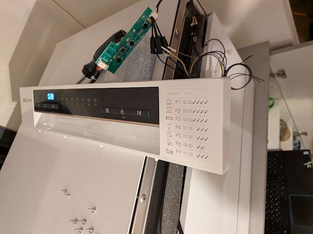
Last November I got myself a small dishwasher, a counter-top model from a local vendor. I was emptying the contents of the dishwasher one evening, and curiosity got the better of me and I ended up unscrewing all the screws in the front panel, just to take a small peek at what’s inside.
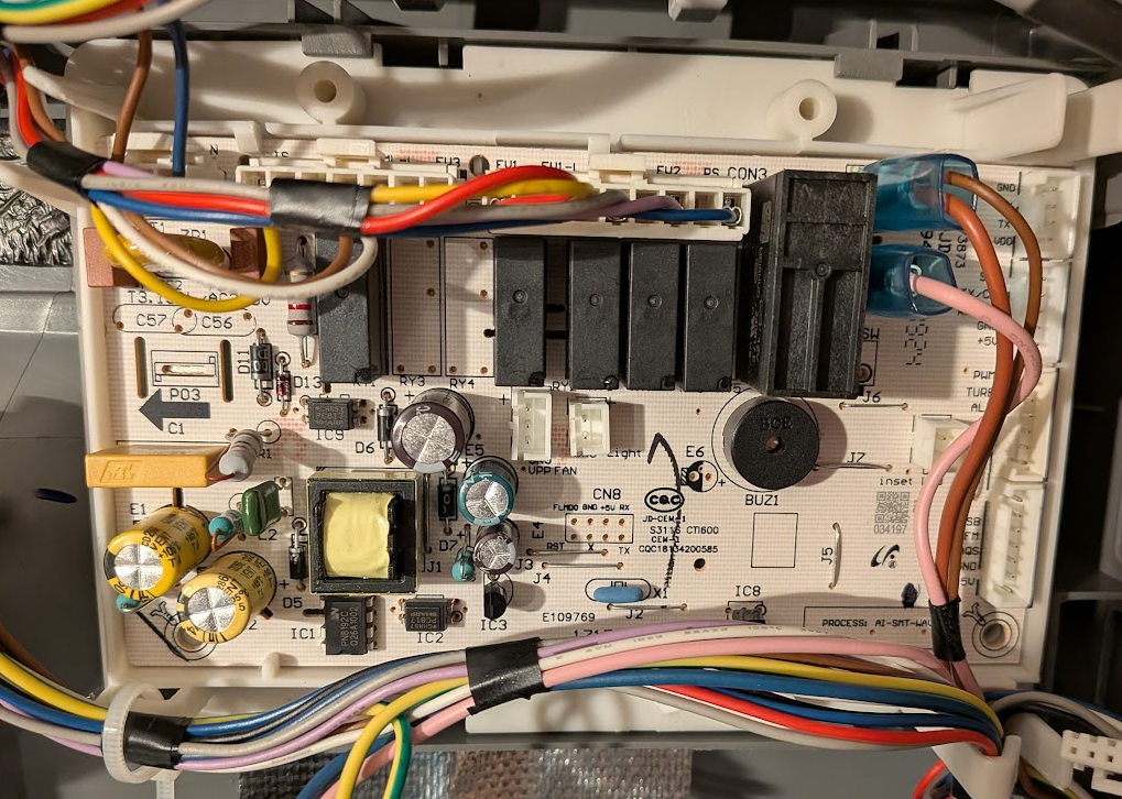
I discovered two small PCBs that make up the front control panel with an umbilical sneaking away into the door. Two more screws removed and I was holding one of the PCBs in my hand. The first thing I noticed was even though it was branded “Electra”, the PCB inside clearly had a Midea part number. The second, a header with 5 wires leading into it, and next to the header the silkscreen read +5v GND RX TX, the kind of header that makes me feel like a moth drawn to a lightbulb.
I promptly got out my logic analyzer and with my laptop in the cupboard, I started listening to the front panel’s conversation with the control board.
From Logic Analyzer to WiFi Sniffer
Using the logic analyzer, I was able to see the data flowing back and forth between the main control board and the control panel, but it was not the best tool for the job. The fact that the dishwasher’s control panel was dangling around, the analyzer’s wires snaking out of it to my laptop in the cupboard, the physical high location and the fact I need to close the door and manually insert the latch so it can operate made the process somewhat cumbersome. To this, there is the fact that the logic analyzer has done its job; I now know the physical link-layer protocol (UART 8N1@9600) and need a way to visualize the data and exploit pattern recognition, not see a stream of on and off states on a wire.
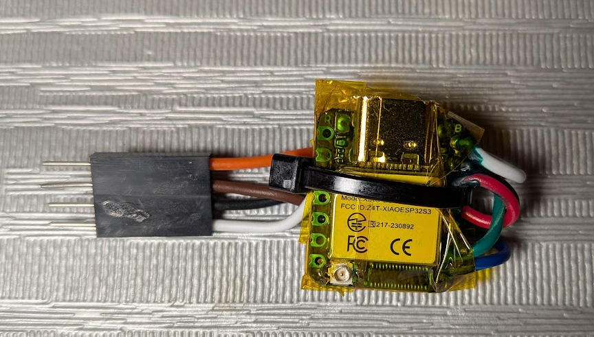
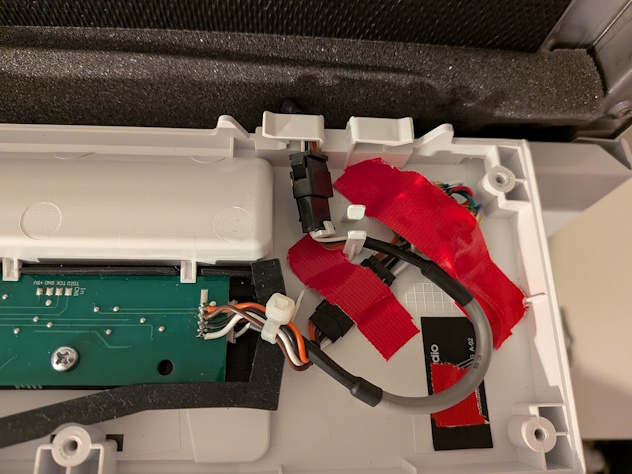
The solution I thought of would solve both my problems. I created a dedicated sniffer based on an ESP32 module, specifically, the XIAO ESP32-S3. Even though I have a plethora of small dev boards, the small form factor of the ESP32 meant that I can hide it in the small gap left between the front panel bezel and the actual door frame, allowing me to button up the front panel. The WiFi capability also meant that I did not need to make holes or have wires coming out of the machine and I could lounge on my couch while watching the dishwasher’s internal communication.
The hardware setup was simple. On the dishwasher side, I prepared it for a sniffer tap by soldering a 4-pin 2.54mm female header to the back of the control panel PCB where the connection is made to the control board. For the sniffer side, I soldered 2 wires for the 5V and GND for power, and to protect the ESP32 inputs, I connected the UART lines via a voltage divider with R1=2.2k and R2=3.3k to produce a safe 3V logic-high level (Formula: Vout = Vin × R2 / (R1 + R2)). It does not matter to what GPIOs the two UART connections are connected to on the ESP32, but it is important to remember that since this is a sniffer, the ESP32 is configured to be receiving on both GPIOs and to not have one incorrectly set as a TX pin, as if the ESP will pull the GPIO pin high or low, it can disrupt the communication between the two boards.
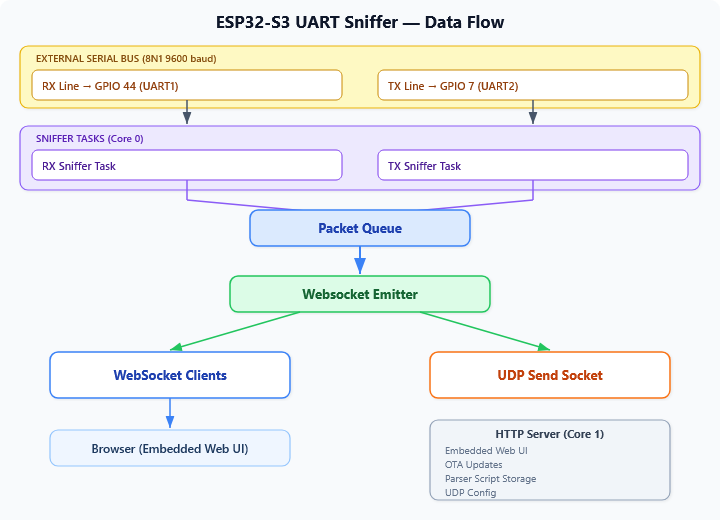
The software setup was also not that complicated. The ESP32 was configured to connect to my local network and just forward those packets over a UDP socket to a static IP address of a container running on my NAS. The container on the NAS just dumped the data into a file that I can access over SMB. Since my NAS is powered on 24/7, I’m passively collecting data as I use the dishwasher and my sample size of packets to analyze grows, all with the benefit of collecting samples from all different types of wash programs, cycles, errors and events, the packets are transmitted at about 10Hz for each direction.
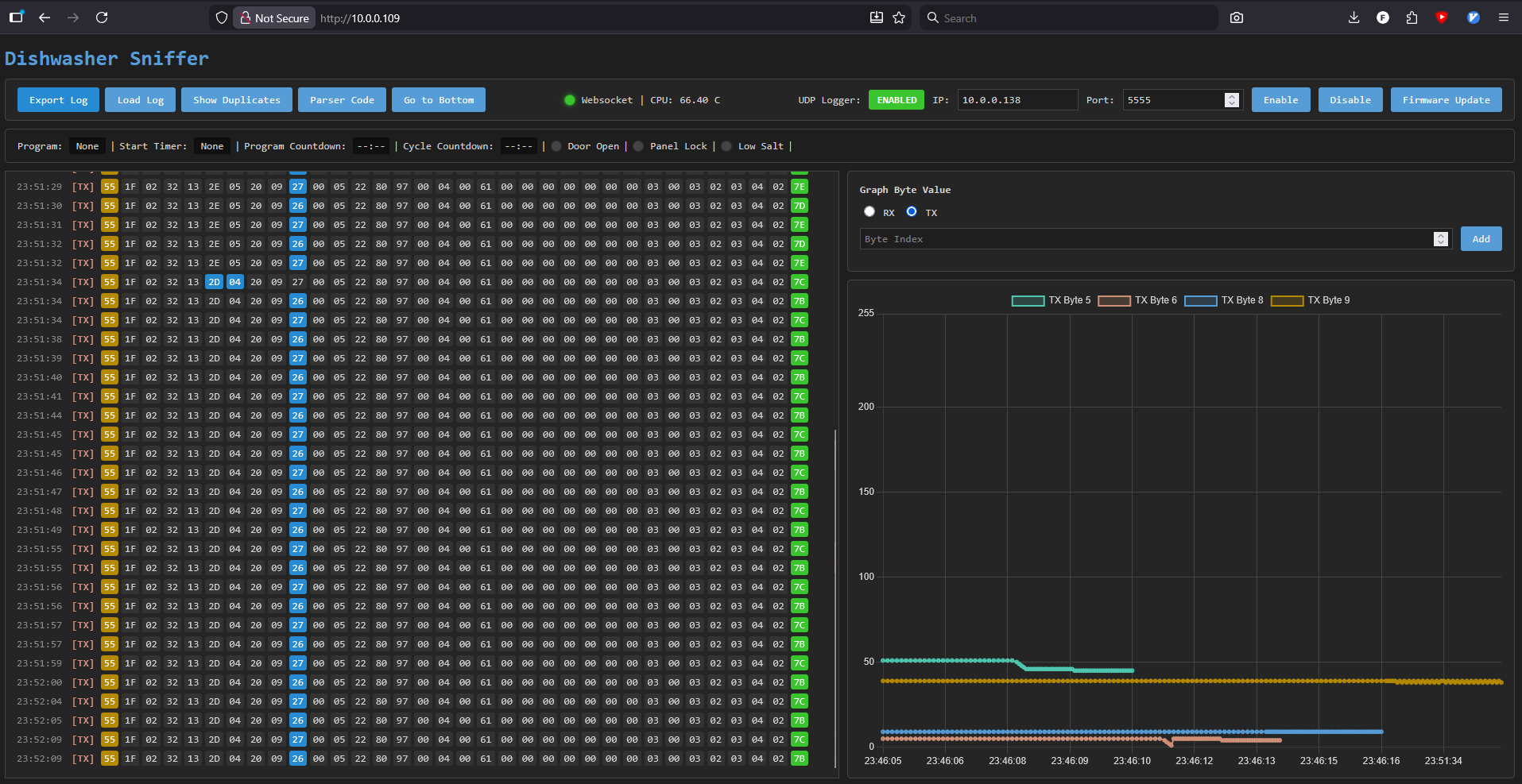
I later added a small web UI with a few more features:
- OTA firmware updates (to fix bugs and add features)
- Enable/Disable UDP streaming and server IP/PORT
- Loading and exporting data from the web UI
- Collapse duplicate packets and show only changes
- ESP32 core temperature logging (the ESP32 is in a small enclosed space)
- Packet byte highlighting
- Binary diff between adjacent packet byte values
- Graphing byte values over time
- Parsing packet bytes and displaying live info
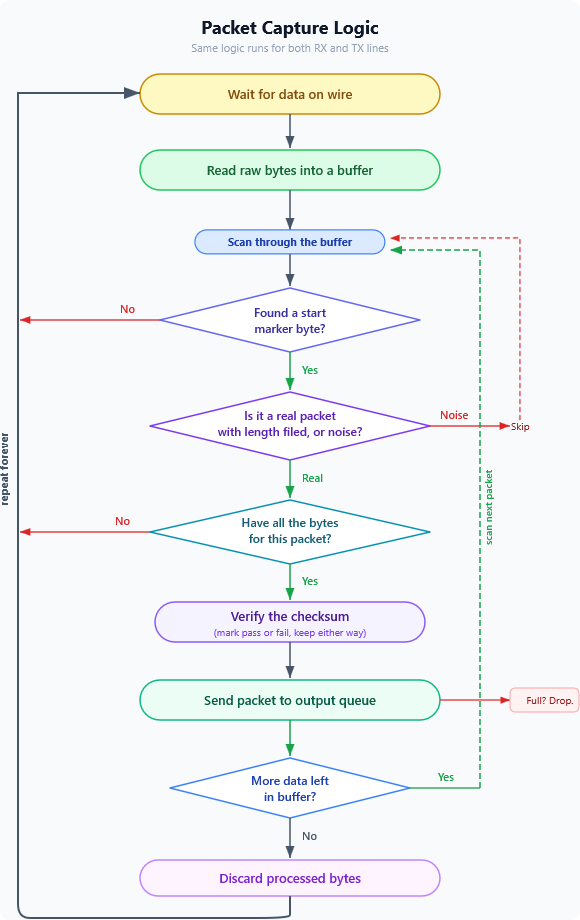
The main data flow on the ESP32 ended up looking something like this:
Protocol Deciphering Aids
Physical Inspection
Up to a point, all my analysis was based on correlating protocol data with external observations: sounds, power consumption, and timing. To understand the remaining mysteries, especially states that seem similar, I wanted to see what hardware actually exists inside.
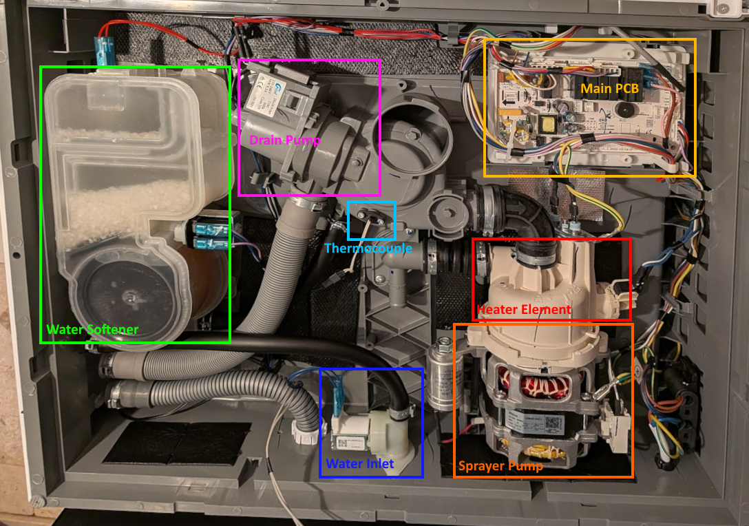
I opened up the machine and inspected the control board. It has printed labels and solder pads for: drain pump, wash pump (high speed), wash pump (low speed), heater, inlet valve, regeneration valve, dispenser, fan, diverter valve, turbidity sensor, lights and more.
On my counter-top unit, several of these are not connected: the fan, lower-speed wash pump, diverter valve, turbidity sensor, etc. The headers are on the PCB, the traces are there, but no wires lead to them. This board is shared across multiple Midea dishwasher models, and I assume the firmware is probably similar if not identical. This helps me filter out false positives (I know I don’t have a turbidity sensor and therefore a sensor reading fluctuating is probably not turbidity). It also confirmed that some values/states may actually not mean anything or correlate to a visual/audio cue as these would be missing on my unit.
The Hidden Test Program
Midea dishwashers have a factory service test program. I found the activation sequence in the service manual, though it was not for my dishwasher model, I tried it and it still worked (; unplug the machine, plug back in and within 60 seconds, while holding down Start/Pause and then press Power to turn the machine on, all this while the door is open. Once the door is closed, the test begins.
The test runs each major component in sequence, one at a time - it isolates individual actuators in a way that normal cycles never do.
Unfortunately, this did not really help in decoding anything interesting apart from specific test-mode only values and a single bit in the system state byte.
Power Monitoring
In the process of trying to figure out some of the protocol bytes described later on, I also added a power monitor plug on the power cord to help in correlation of various components that are silent, such as the heater element ON/OFF state and various valves.
Deciphering The Packet Structure
With the sniffer running and collecting data, the first task is to understand the raw bytes. I have two streams, one from each UART line, and at this point they’re just sequences of numbers. I don’t know where meaningful fields are, which bytes matter, or what any of it means. However, several things stand out.
Byte 0 - A Constant Start Marker
The very first byte is 0x55 in every single packet, both directions. It never changes. In binary, 0x55 is 01010101 - a classic alternating bit pattern commonly used as a synchronization preamble in serial protocols. The alternating edges help hardware lock onto the bit timing, and the distinctive pattern makes it easy to detect framing errors (wrong baud rate, shifted alignment). This is the packet start marker.
The Last Byte - Something Noisy
The last byte in each packet changes constantly with no obvious pattern. More importantly, whenever any other byte changes, this one almost always changes too. This behavior is the hallmark of a checksum or CRC, a signature like mark to detect transmission errors.
I tested common single byte checksum algorithms, XOR of all bytes, modular sum (sum(packet) & 0xff), several CRC-8 polynomials. None matched. I tried including and excluding byte 0. Still nothing. Either the algorithm is non-standard, or I’m including bytes in my calculation that shouldn’t be there.
Byte 1 - The Key to the Checksum
Byte 1 is constant within each direction but differs between them: 0x1f (31) for TX packets, 0x10 (16) for RX packets. The total packet sizes are 34 and 19 bytes. Subtract the start marker, this byte itself, and the suspected checksum: 34 − 3 = 31, 19 − 3 = 16. That’s a match! byte 1 is a data length field.
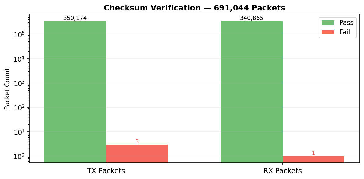
This was the missing piece. I re-ran the checksum calculation, this time starting from byte 2 (after the preamble and length) through the penultimate byte, and immediately got a hit on the modular sum. sum(data_bytes) & 0xff that was it. Running the checksum calculation against all data captured at the time (691,043 packets) revealed a 99.9994 pass rate, that’s five nines in a row and good enough for me.
The Packet Frame Structure
| Field | Size | Value |
|---|---|---|
| Preamble | 1 byte | Always 0x55 |
| Length | 1 byte | 0x1f (TX) or 0x10 (RX) |
| Data | n bytes | Payload |
| Checksum | 1 byte | sum(data bytes) & 0xff |
With framing solved, I updated the sniffer firmware to detect packet boundaries in real time, reject corrupted packets, and recover gracefully when it powers on mid-stream.
Identifying the data itself is a new challenge. I started by graphing every byte position as a line over the packet index and looked for visual patterns. A flat line means a constant. A noisy line might be a counter, a measurement, or a checksum. Spikes might correlate with events. The human eye is surprisingly good at spotting structure in this kind of visualization.
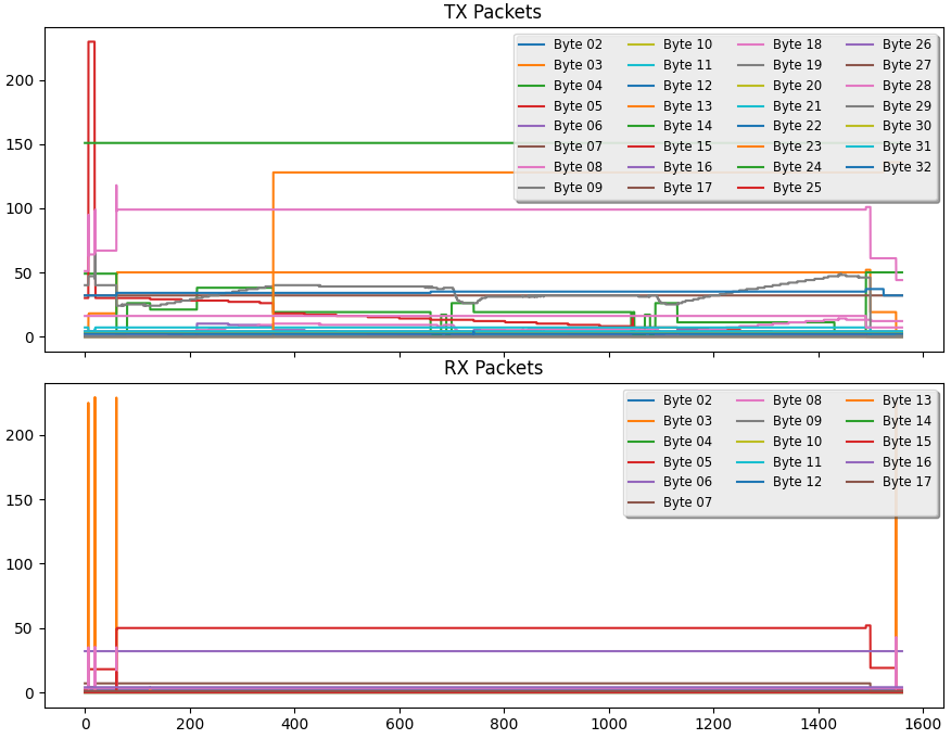
At this point I added the web UI features so I can track changes and graph in real time.
In the next paragraphs, I’ll describe the byte values and their meanings as I have deciphered them so far, starting with the TX packets from the main board to the panel, then the RX packets from the panel to the main board. It’s important to take the information presented here with a grain of salt, as my methodology is based on correlation and inference, not direct access to the firmware or hardware signals. I have high confidence in some bytes (e.g., the system state byte) and more uncertainty in others (e.g., the operation state byte). I welcome any corrections, insights, or additional observations from others who may have access to similar machines or data.
The TX Packet - The Main Board Reports
The TX packet (main board -> door panel) is 34 bytes and far more active than the RX packets, it reflects the current system state and therefore I’ll start with TX first. This is the main board telling the panel what’s happening inside the machine - temperatures, timers, operation states, errors.
My methodology here was that when I run wash cycles I simultaneously watch the live byte values, listening to the machine. By correlating byte changes with physical observations such as sounds, power draw, time passing - I could assign meaning to each byte.
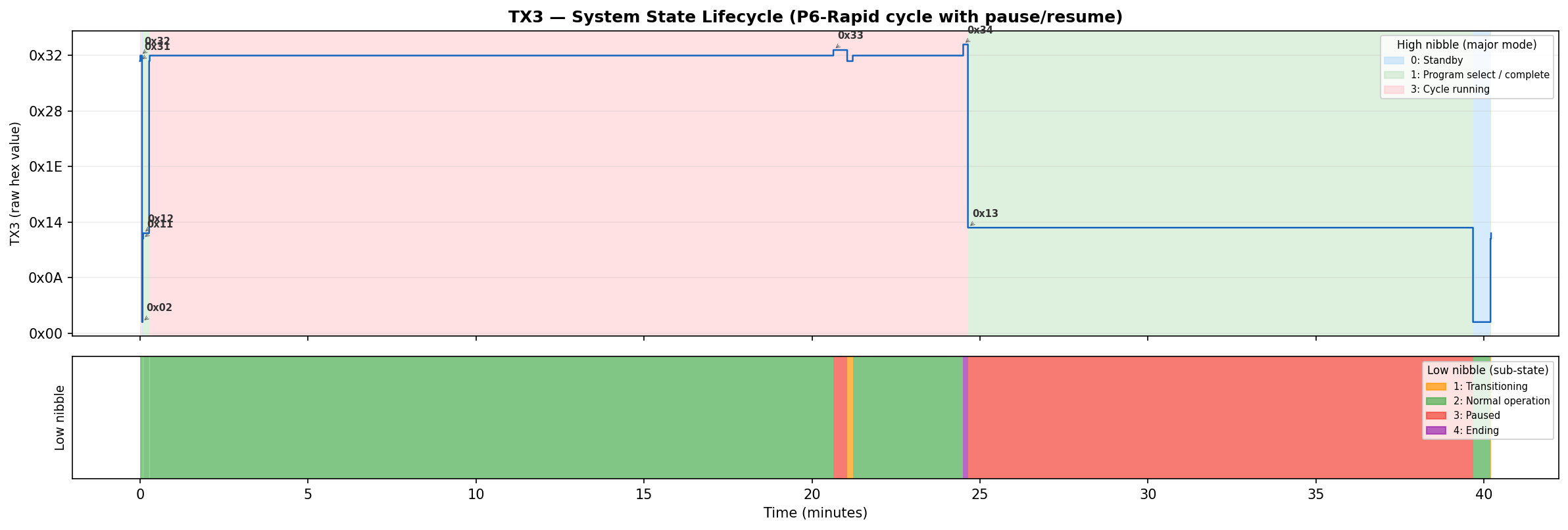
TX3 - The System State
TX3 took the longest to fully decode because it packs information into two nibbles.
My approach was to log TX3 values during every kind of event I could produce: powering on, starting a cycle, pausing mid-cycle, opening the door, letting a cycle finish, triggering an error, and running in test mode. By mapping TX3 values to these known events, the structure emerged:
The high nibble (upper 4 bits)
| Value | State |
|---|---|
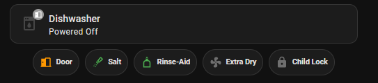
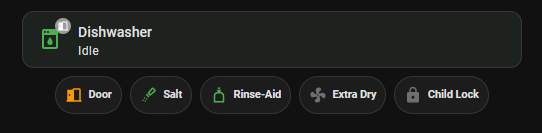
| 0 | Powered Off |
| 1 | Idle |
| 2 | Timer Countdown |
| 3 | Running |
| 4 | Error |
| 5 | Hardness Setting Mode |
| 8 | Test Mode |
The lower nibble (lower 4 bits) is a sub-state within that mode.
| Value | State |
|---|---|
| 1 | Transition |
| 2 | Normal |
| 3 | Paused |
| 4 | Ending |
So 0x32 means “cycle running, normal.” Opening the door mid-cycle changes it to 0x33 - “running, paused.” When the cycle finishes, it briefly shows 0x34 - “running, ending” before transitioning to idle, while the machine gives its ending beeps. For test mode, 0x82 means “test mode, running.”
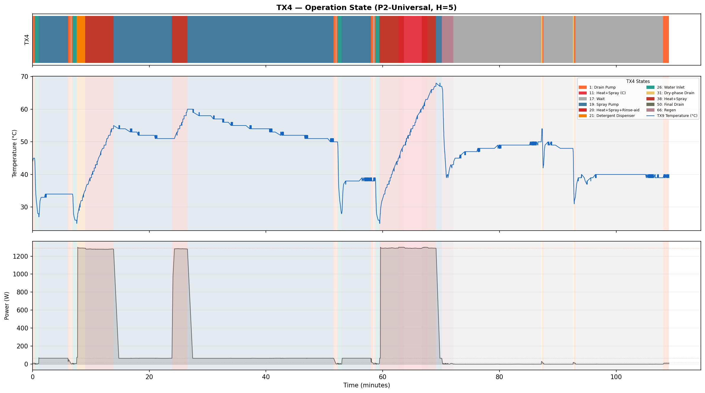
TX4 - The Operation State
TX4 was the hardest byte to decode, and the most interesting. Its value changes whenever the machine transitions between operations. I can hear the drain pump start and TX4 changes. I hear the water inlet valve open and it changes again. The spray pump kicks in - another value. Heating starts - yet another.
To build a complete picture, I waited until I had logged cycles across all programs, when possible I noted anything I could physically observe throughout: what sounds the machine was making, whether I could hear the spray pump or the drain, humming and patterns. I even added just for this byte a power monitor to monitor power for power analysis and correlation.
Here is every TX4 value I observed during normal wash cycles:
| TX4 | Operation | Notes |
|---|---|---|
| 0 | Idle | Silent, nothing happening |
| 1 | Drain pump | |
| 11 | Heat + Spray | Only in rinse phase |
| 17 | Wait | Silent, passive idle mid-cycle |
| 19 | Spray pump | Spray only, no heating |
| 20 | Heat + Spray + Rinse-aid | Only in final rinse, never in Rapid |
| 21 | Heat + Spray + Detergent | Only on start of main wash |
| 26 | Water inlet | |
| 31 | Regeneration Dry-phase Pre-drain | Only observed in cycles with TX4=66, just before a standard drain in the dry phase. |
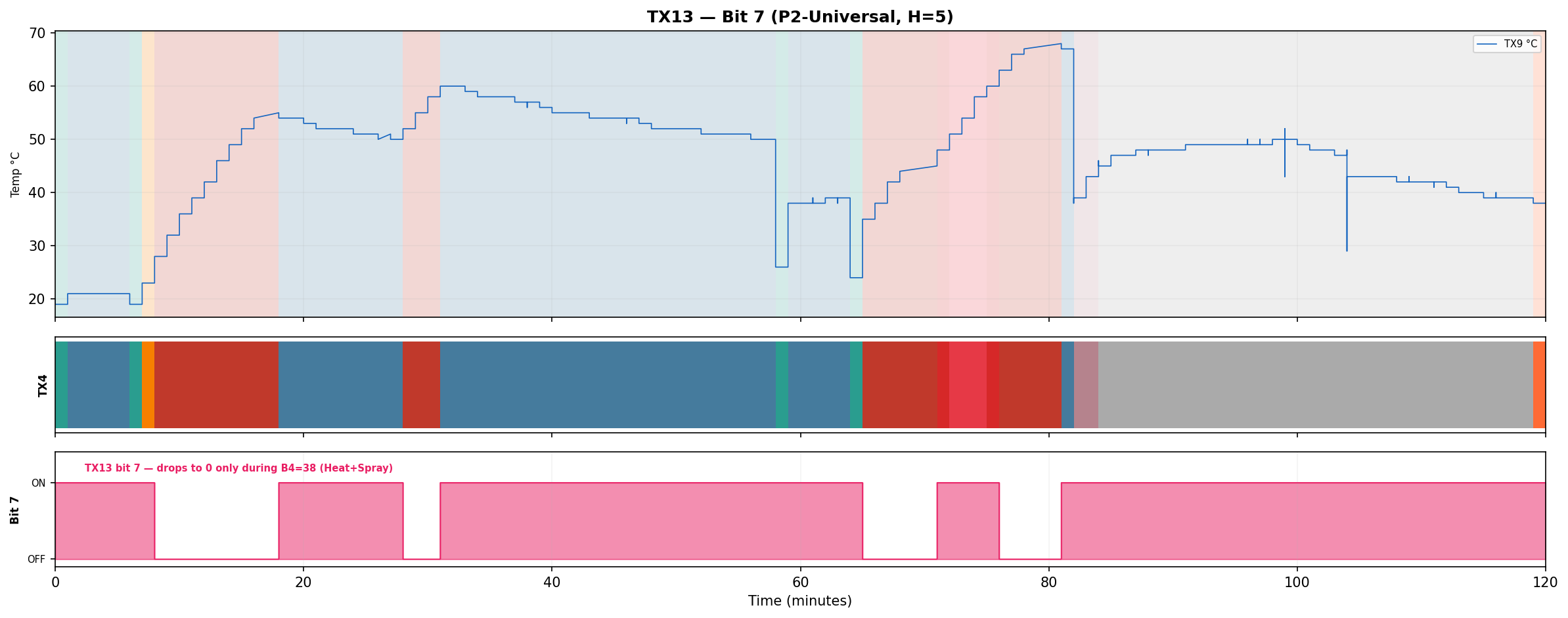
| 38 | Heat + Spray | When set, TX13:7 sets to OFF for the duration of the operation. |
| 48 | Pulsed spray | Spray pump duty-cycled |
| 49 | Prog Display Idle | Idle while program on display before cycle starts |
| 50 | End Display Idle | Possible idle state after program ends |
| 66 | Regeneration valve | Opens brine regeneration valve, flushing cold brine through softener into sump. Observed at the end of the last rinse cycle, causes rapid temp drop (about -30 C), never observed in Rapid. |
The following values appear only in the factory test program:
| TX4 | Operation | Notes |
|---|---|---|
| 6 | Brine regeneration valve | Regen valve test, ~13 s |
| 52 | Test init | |
| 53 | Test complete | |
| 54 | Test fill | Water inlet during test |
| 55 | Test spray + heat | Heats to 57 C |
| 58 | Detergent / rinse aid test |
Fourteen different values during normal cycles, plus six more in the test program. Some produce distinctly different effects (draining vs. filling vs. spraying), while others initially appeared identical: TX4=11, TX4=20, TX4=21, and TX4=38 all involve the spray pump and heater running simultaneously with similar power draw. After logging all programs, closing the dispenser door back up mid cycle and correlating with timing and context, the differences became clear:
- TX4=38: Heat + Spray, appears in main wash, rinse and as a heating boost in long main washes (TX13:7 is OFF).
- TX4=20: Heat + spray with rinse-aid dispenser actuation - Only appears in the final rinse of non-Rapid programs (rapid does not use rinse-aid).
- TX4=21: Heat + spray with detergent dispenser actuation - Only at the start of main wash.
On the control PCB, I noticed there was only 1 connection to the dispenser units. The dispenser unit is most likely to be a wax motor that extends a plunger to open the compartment and let the detergent or rinse-aid out, the same plunger is used for both detergent and rinse-aid compartments and the actuation time changes the extenstion depth, a short momentary actuation for the detergent compartment at the start of the main wash, and a longer actuation for the rinse-aid in the final rinse, popping the detergent door open again in the process (it it was closed again).
The only phase that is not clear yet is TX4=11 it’s similar to TX4=38, but only appears in rinse phase, interestingly TX13:7 is ON (opposite of TX4=38). I’m yet to figure out the difference between TX4=11 and TX4=38, they do not seem to differ in temperature rise rate or power consumption.
Is TX4 a Bitfield?
My first hypothesis was that TX4 must be a bitfield - each bit corresponding to a component. One bit for the drain pump, one for the heater, one for the spray pump, etc. Different combinations of components ON/OFF would produce different numeric values, and overlapping bits would explain the duplicates. This is how many embedded systems control multiple actuators from a single register.
To test this, I took the four values where I observed both spraying and high power draw from the heater. If a “heater bit” exists, it must be 1 in all four values:
| TX4 | Binary | b6 | b5 | b4 | b3 | b2 | b1 | b0 |
|---|---|---|---|---|---|---|---|---|
| 11 | 0001011 | 0 | 0 | 0 | 1 | 0 | 1 | 1 |
| 20 | 0010100 | 0 | 0 | 1 | 0 | 1 | 0 | 0 |
| 21 | 0010101 | 0 | 0 | 1 | 0 | 1 | 0 | 1 |
| 38 | 0100110 | 0 | 1 | 0 | 0 | 1 | 1 | 0 |
No column is all 1s. There is no “heater bit”, I tested this for some other components as well, and the same result came up. The values are not bitfields.
TX4 is not a bitfield - it’s probably an FSM index Each value is probably an index into a lookup table baked into the MCU firmware or a state represented in a finite-state-machine, where each entry specifies which combination of actuators to activate. This means the mapping between TX4 values and physical actions isn’t derivable from the bits; you have to observe each one individually. It also means the reason for multiple values producing the same physical effect must lie somewhere else. It’s possible that I’m missing some operation that is happening and I cannot observe or think about, it’s also possible these values are part of operations that my machine does not have, as I mentioned earlier, the control PCB is generic across models, the 4 different values I observed for the sprayer+heater combo might on a different machine operate two different heating elements/power levels or a diverter valve for spraying from the top, then the bottom, then both.
Byte 4 is puzzling, I would love to know why it behaves this way and to have solid and concrete evidence to what is actuated at any given stage/value, however, I am not going to disassemble the control board PCB at this time to start firmware dumping or connecting sensing wires to every pin and component on the PCB to figure out if it’s actually actuating missing components. I have limited myself to external observations only and the sniffed packets.
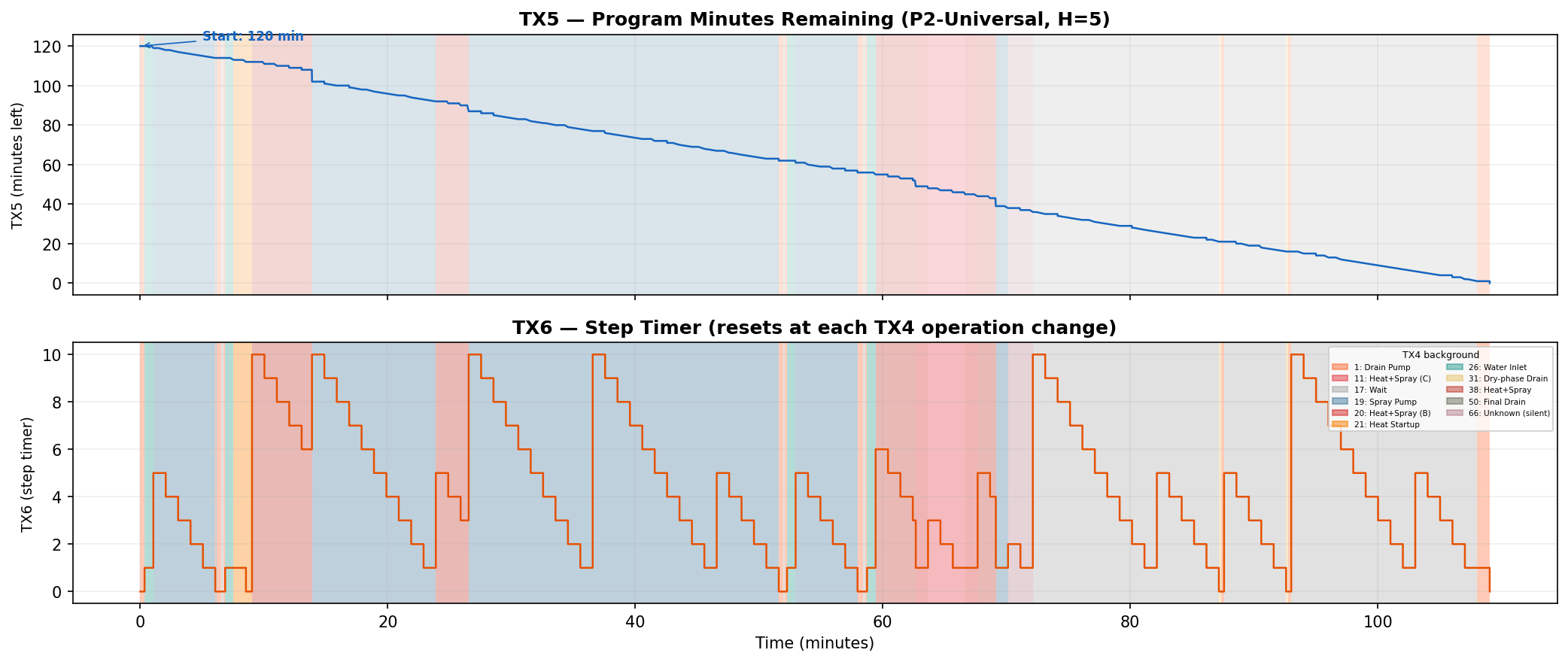
TX5 - Program Minutes Remaining
From the graphs, I noticed a byte that decreases by exactly 1 roughly every 60 seconds and never increases during a cycle. Comparing its starting value to the program durations listed in the manual: ECO starts at 230 (manual says program time is 3h 50m), Rapid starts at 30 (manual says 30 min), 90-min wash starts at 90 (no surprise). This is the cycle time remaining in minutes - the same value shown on the LED display. Another observation that corroborated this was that in the graph, there is sometimes a larger skip, of approx. 7 minutes, that matches an observation I made earlier that the dishwasher took less time to complete a program than I expected, about 5-10 minutes, I do not know why the time skips like that, but I have observed this in many cycles (maybe a change in heating time/reaching target temperatures?).
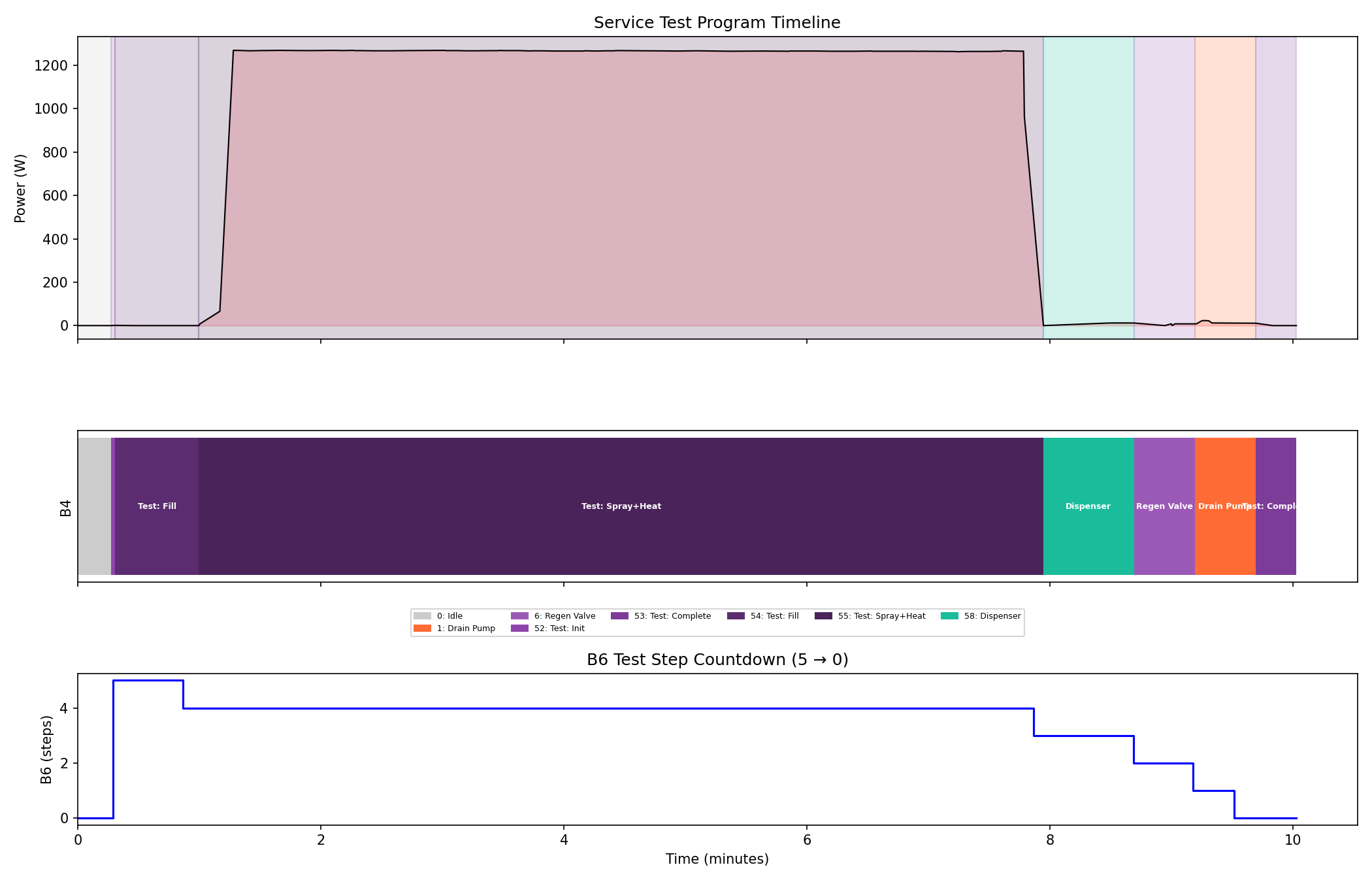
TX6 - Step Timer
TX6 also counts down, but it resets to a new value periodically throughout the program. Each reset coincides with the machine audibly transitioning to a new operation (e.g., I hear the spray stop and the drain pump start, and TX6 resets). It seems to track the minutes remaining in the current step before the machine moves on to the next. In a test mode program I discovered later, it seems to track the test-program current step (counts from 5 to 0).
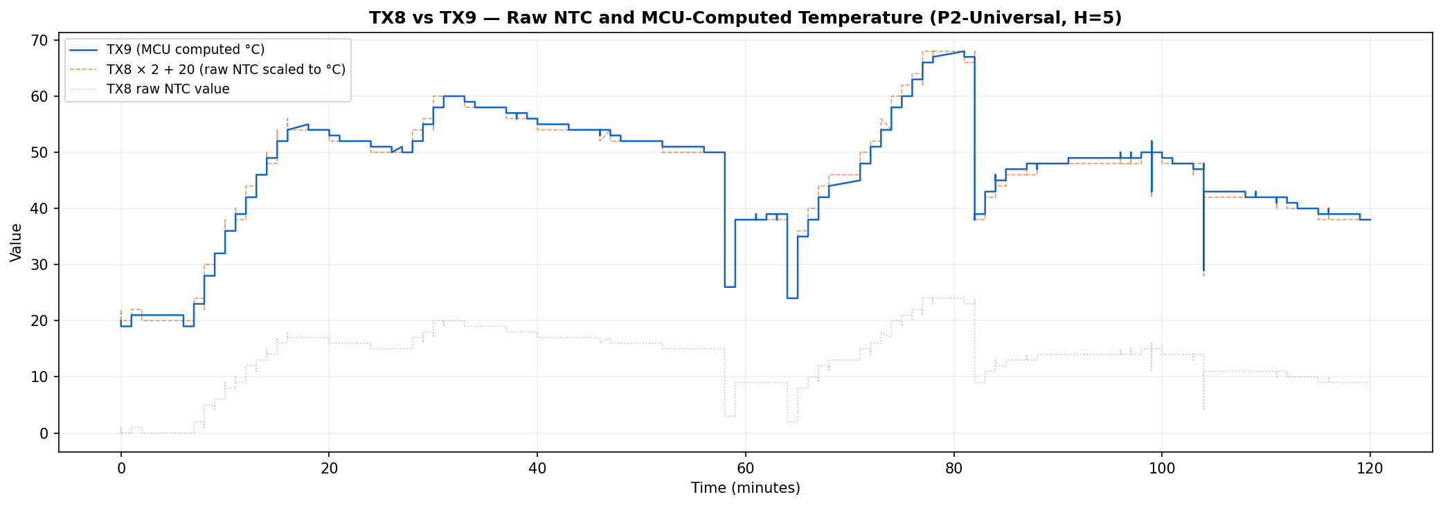
TX8 and TX9 - Water Temperature
TX9 has an interesting pattern, sometimes in climbs, plateaus or drops rapidly. It also seems to be in lock-step with TX8, however TX8 is on a different scale.
Watching this byte through the program cycle, it rises with heated rinses, but not cold rinses, it dips when the drain pump is active, and drops rapidly when the water inlet is opened to refill the dishwasher after a heated rinse. Comparing TX9s peaks and plateaus with the known wash and rinse temperatures for specific programs in the manual indeed shows that it’s reflecting the current water temperature, interestingly, if a program is not running but selected, it reflects the program’s main wash target temperature.
TX8 just seems to be a scaled version of TX9 but seems to fluctuate even when a program is selected but not running. I located the temperature sensor (an NTC) in the sump under the filter. Holding a lighter to this briefly made the value spike, putting an ice cube on it dropped it down.
From these observations I can confirm that TX9 is current water temperature in Celsius when program is running, target temperature in Celsius when program selected. TX8 is probably a raw reading of the sensor value and using the formula (val * 2) + 20 brings the value close to the TX9, within 1-2 deg C.
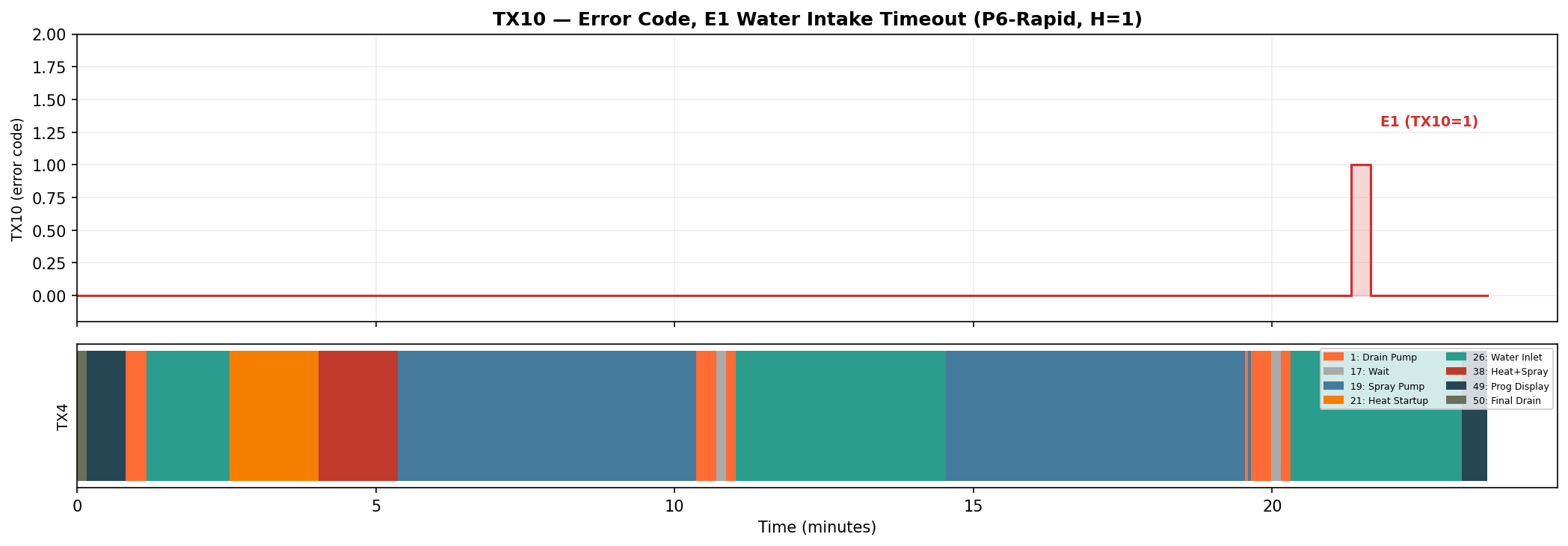
TX10 - Deliberately Breaking Things
The passive observation approach works well for understanding normal operation, but some bytes only become meaningful during exceptional conditions. To explore error handling, I deliberately caused faults while watching the data.
The manual specifies 4 error states:
| State | Meaning |
|---|---|
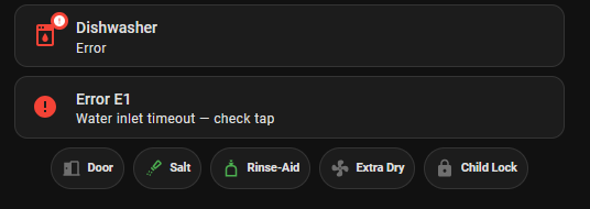
| E1 | Long water inlet time |
| E3 | Long water heating time |
| E4 | Flood alert |
| Ed | Communication Error |
I flipped the dishwasher on its back and on the bottom cover, there is a sensor to detect leaks from the various components. I used a small screwdriver to lift the float switch and 2 seconds later, TX10 became 4.
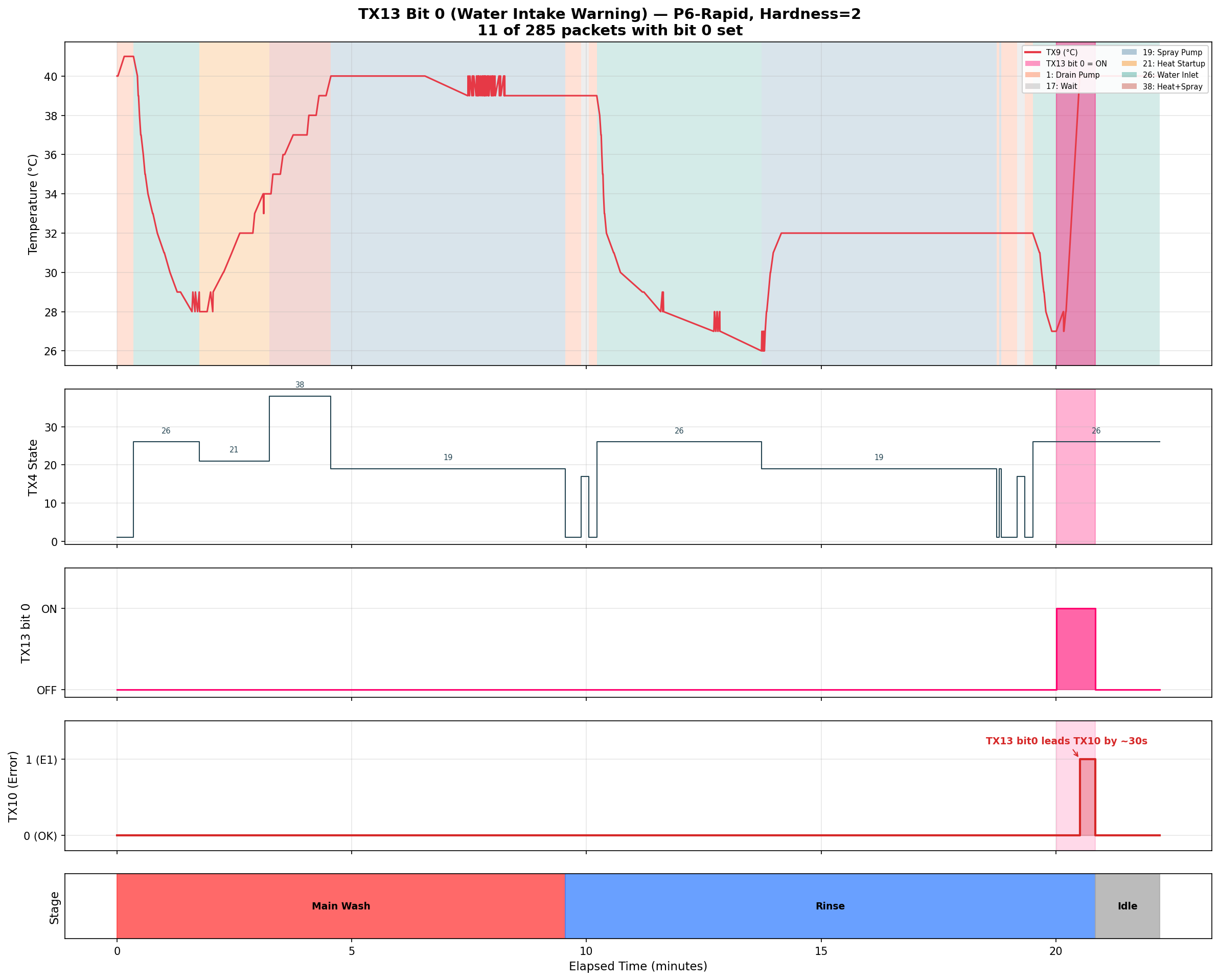
In a coincidence, I ran a rapid wash one evening and out of the blue, I got an intake error on the second rinse cycle. Apparently, some work was being done on the mains water pipe and there was a planned water shutoff for 6 hours which started exactly after I started the dishwasher, this gave me a real world test of the intake error, Thankfully, this was on the second rinse and the dishes were already clean :).
I directly observed two of these: the flood sensor test produced TX10=4 (E4), and a real-world water shutoff later produced TX10=1 (E1). The remaining two, 3 for heating timeout (E3) and 0x0d for communication error (Ed), are inferred from the manual’s error codes but I have not observed them in the protocol data. Based on this, TX10 is a simple error enum where 0 means no error.
TX11 - Program Code
TX11 holds the current program code. By cycling through the program settings on the machine, it maps to - 2 for Intensive, 3 for Universal, and so on. This is the main board telling the front panel what program it’s currently set to. TX11 value during idle and test mode is 0.
| TX11 | Name | Display | Duration | Stages (from manual) |
|---|---|---|---|---|
| 0 | No Program | - | - | - |
| 2 | Intensive | P1 | 140 min | Pre-wash 50°C, Main wash 70°C, Rinse, Rinse, Rinse 70°C, Dry |
| 3 | Universal | P2 | 120 min | Pre-wash, Main wash 65°C, Rinse, Rinse 70°C, Dry |
| 4 | ECO | P3 | 230 min | Pre-wash, Main wash 45°C, Rinse 60°C, Dry |
| 5 | Glass | P4 | 75 min | Main wash 45°C, Rinse, Rinse 60°C, Dry |
| 6 | 90 Minute | P5 | 90 min | Main wash 65°C, Rinse, Rinse, Rinse 70°C, Dry |
| 7 | Rapid | P6 | 30 min | Main wash 40°C, Rinse, Rinse |
| 16 | Self-Clean | P7 | 80 min | Main wash 70°C, Rinse, Rinse 65°C, Dry |
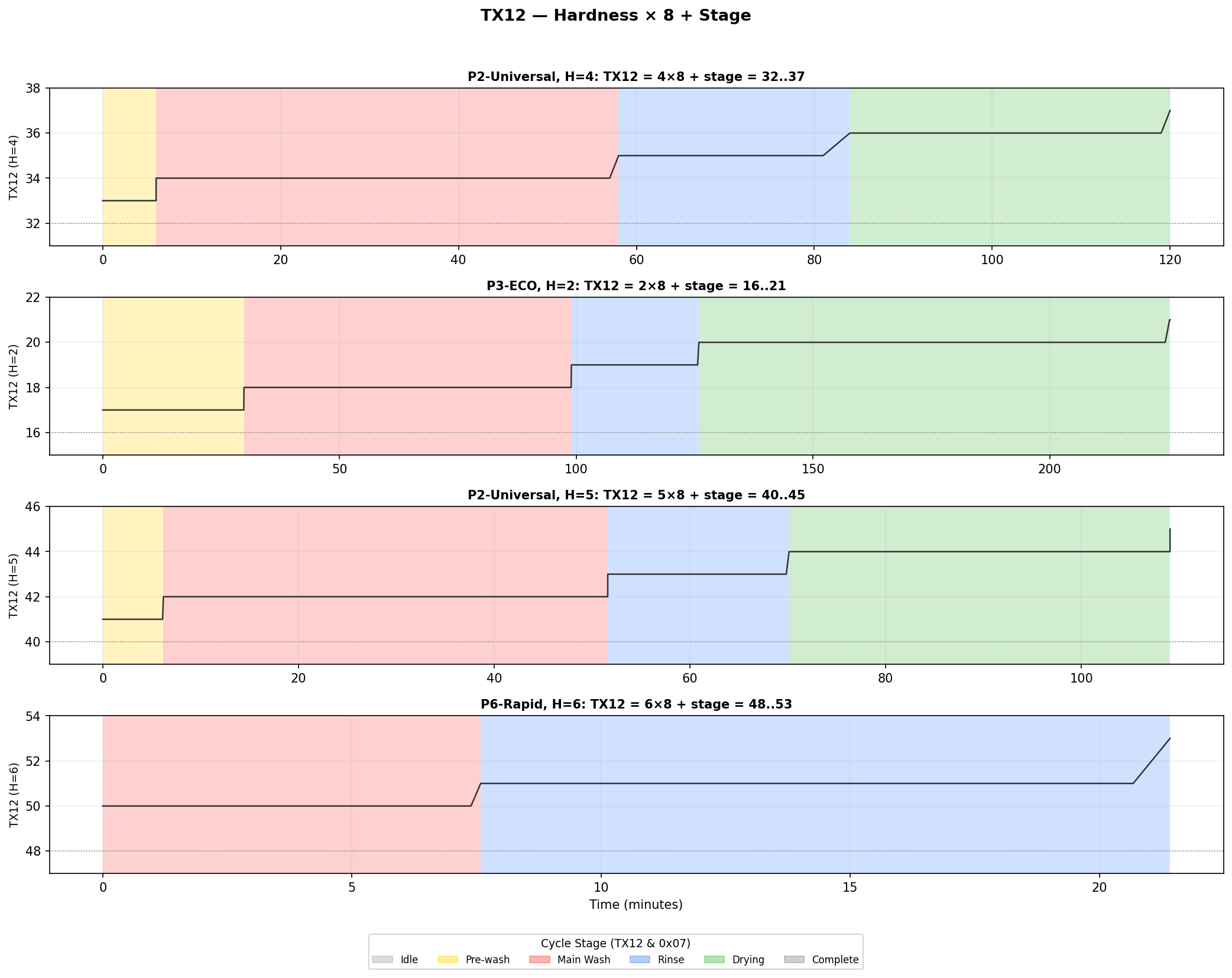
TX12 - When One Byte Carries Two Values
TX12 was one of the most satisfying bytes to crack, because it required multiple experiments at different machine settings to reveal its structure.
During a cycle with the water hardness set to 5, TX12 showed values like 40, 41, 42, 43, 44, 45. These increased as the cycle progressed - 40 at the start, 41 during the first wash, higher values in later phases. But the numbers were too large for a simple stage counter, and the starting value of 40 didn’t make sense either.
The breakthrough came when I changed the hardness setting and ran another cycle. At hardness 4, the values shifted to 32, 33, 34, 35, 36, 37. I changed hardness again and at hardness 2: 16, 17, 18, 19, 20, 21. The difference between consecutive hardness levels was always exactly 8. The pattern:
TX12 = hardness × 8 + stage
To unpack the two values,
TX12 >> 3gives hardnessTX12 & 0x07gives current program stage
The low bits cycle through values 0–5 as the program progresses, and those map neatly to the wash phases:
| Stage | Meaning |
|---|---|
| 0 | Idle |
| 1 | Pre-wash |
| 2 | Main wash |
| 3 | Rinse |
| 4 | Dry |
| 5 | Complete |
I verified this formula across all hardness levels with zero mismatches across thousands of packets.
TX13 - Testing Every Sensor
I wanted to find where sensor states are reported, this is maybe the only useful thing I can actually get from this mini research project, an integration to Home Assistant to tell the rinse aid or water softener salt is low would be nice, or remind me to open the door at the end of a cycle to achieve better drying results.
I decided to trigger the dishwasher and take it out of its comfort zone. The first bit detected was bit 3, it toggles on when I open the door and back off when closed, I made sure to open the door mid-program and still, same bit triggers.
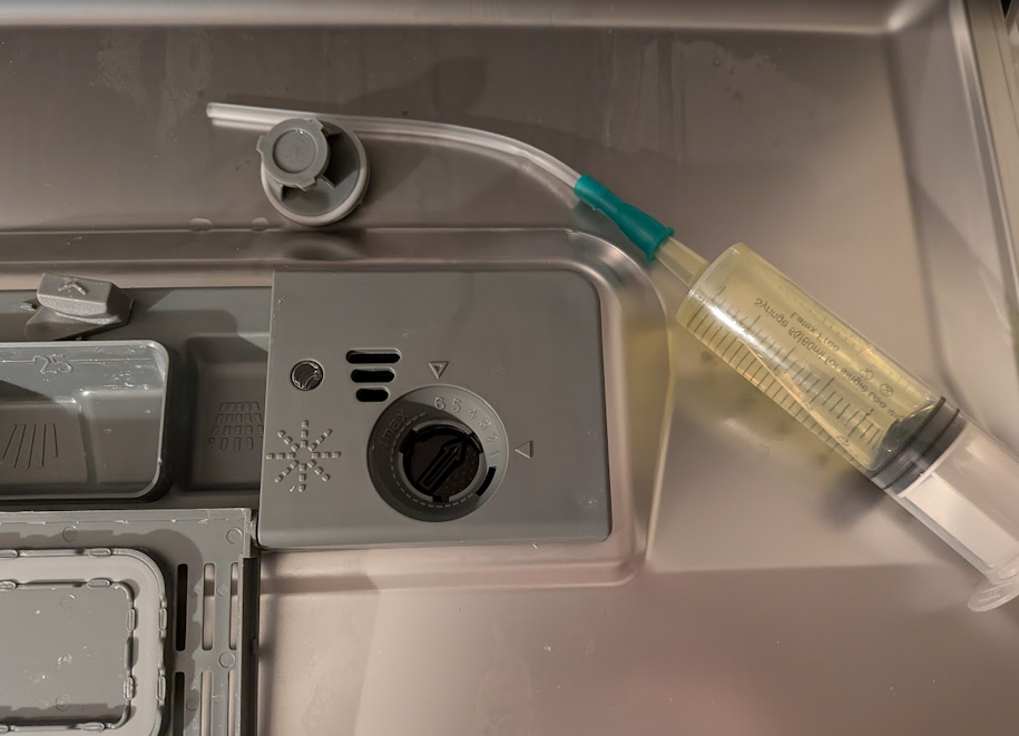
The rinse aid was a bit harder to trigger, There is no easy and clean way to empty the rinse aid tank. I opened the cap and using a large 60cc syringe and a flexible medical feeding tube, I sneaked it into the narrow opening and pumped out my patient’s stomach. At first I could not get the sensor to trigger, it was a while before I noticed that the door needs to be almost shut (in an upright position) for the sensor to trigger, which makes perfect sense that if the door is open, it cannot measure a low level as its operating position is closed. Another discovery was that if I swing the door shut relatively fast, which causes the liquid to slosh, the sensor triggers for a brief moment. This caused TX13 bit 5 to change to 1 whenever it triggered.
The salt level triggering was far easier. I just opened the salt refill cap and started sucking out all the brine from the brine tank. The salt tank is surprisingly large but after much suck-and-dump it finally turned on the low salt indicator on the front panel, and with it, bit 4 of TX13 flipped to 1. When I refilled the tank with salt and water, it indeed turned itself off.
| Mask Value | Bit Index | Description |
|---|---|---|
0x01 | 0 | Water Inlet Warning (Set 30 seconds before E1 error) |
0x08 | 3 | Door Open |
0x10 | 4 | Salt Reservoir Low |
0x20 | 5 | Rinse-Aid Reservoir Low |
No other actions on my part caused other bits in this byte to flip, however, throughout a program cycle I did notice the following changes that I cannot explain yet:
Bit 1: Only observed to toggle during the test-mode program, toggles to 1 at the test init stage and toggles back to 0 for the water inlet stage and then toggles back to 1 when heater and sprayer test starts. Does not clear when test completes, clears on dishwasher power cycle.
Bit 7: This bit is ON except when TX4=38 (full-power heating) and during the entire test program. On my unit with a single heating element, the purpose is unclear - it could be an interlock or relay control flag relevant to models with dual heating elements or other hardware.
TX15 - Extra Options
The only real extra option my dishwasher has is an “extra-dry” setting. When enabling the extra-dry, the value of this byte changes to 0x02, this is a bitfield with bit 1 indicating extra-dry option and on higher end models may have other bits for options such as half-load, sanitize, auto door open and more, however, at this time I cannot confirm.
TX16 - Hardness setting
This byte reflects the current set water hardness setting. Its value changes only when setting a new water hardness setting manually or after running the test-mode program that resets the water hardness level to 4 (the factory default).
TX28 - Last Program Run
This byte seems to reflect the last program that was completed, it’s observed updating to the current program code at the end of a completed program cycle.
Other TX Bytes
For the following bytes in the table, I do not have a good explanation as to what they do as for most of them the values are constant or have no pattern I can recognize:
| Byte | Value | Notes |
|---|---|---|
| TX2 | 0x02 | Maybe protocol version (matches RX2)? |
| TX7 | 0x20 | Const (matches RX6) |
| TX14 | 0x97 | Const |
| TX17 | 0x00 | Const |
| TX18 | Variable | Some kind of settings digest. Changes with program, timer, extra dry, and hardness selections. Formula unknown. |
| TX19 - TX25 | 0x00 | Const |
| TX26 | 0x03 | Const |
| TX27 | 0x00 | Const |
| TX29 | Variable | Only observed single cycle where value was already set to 0x02 before cycle start. |
| TX30 | 0x03 | Const |
| TX31 | 0x04 | Const |
| TX32 | 0x02 | Const |
The RX Packet - The Control Panel
The RX packets flow from door panel -> main board, it’s only 19 bytes, and most of them flatline during entire wash cycles. The action happens almost exclusively when I physically interact with the control panel.
RX3 - Button Presses
I noticed that RX3 spikes briefly and returns to 0x00, and the spikes correlate exactly with me pressing buttons on the front panel. To verify, I systematically pressed each button while watching the live data. Power on, Power off, Program select, Start/Pause. Each press produces a single spike to the button’s value, then immediately drops back to 0x00, the panel sends the button code, and then settles back to 0x00. Not all buttons send their own code, and code 0xe5 is used, this is probably since the control board can observe the changes requested from other RX bytes (hardness level, extra dry) or, such as in the case of the delay timer, the timer is in the front panel and not the control board (see RX8).
Observed values:
| Value | Hex | Button | Notes |
|---|---|---|---|
| 225 | 0xe1 | Power ON | Turn on the machine |
| 226 | 0xe2 | Power OFF | Turn off |
| 229 | 0xe5 | Program Btn, Delay Start Btn, Extra Dry Btn | |
| 233 | 0xe9 | Child Lock ON | Hold 3 seconds to toggle |
| 238 | 0xee | Child lock OFF | |
| 0 | 0x00 | Clear | No button code to report |
RX4 - Panel State
RX4 reflects the Extra Dry setting as a latching state: 0x02 when Extra Dry is active, 0x00 when off. Unlike a momentary button press, this value persists at 0x02 for the entire cycle duration while Extra Dry is enabled, and resets to 0x00 when the cycle completes or the machine powers off.
RX5 - System State Mirror
Seems to mirror TX3 (the main board’s system state) but with a delay of a few milliseconds. Whenever TX3 changes, RX5 changes to the same value shortly after. Since RX packets flow from the panel to the main board, this is the panel echoing the main board’s current system state back, likely as an acknowledgment.
RX7 - Program Selection / Mirror
When cycling through wash programs, RX7 steps through: 2, 3, 4, 5, 6, 7, 16, then wraps back to 2. This is the selected program code as seen in TX11.
RX8 - Event Type Byte
When changing settings or pressing buttons on the front panel, RX8 looks like it’s sending an event type to the control board. Value 0x0b triggers after water hardness settings menu exits back to the default program display.
| Value | Event |
|---|---|
0x03 | Idle |
0x0b | Settings Saved |
0x23 | Button Press |
0x2b | Power Off |
0x27 | Start/Pause when in test mode |
The following table describes RX8 relationship with RX3:
| RX3 Val | RX8 Val | Button Val | Event |
|---|---|---|---|
0x00 | 0x03 | - | Idle |
0xe1 | 0x23 | Power ON | Button Press |
0xe2 | 0x2b | Power OFF | Power OFF |
0xe5 | 0x23 | Program/Timer/Ext. Dry Buttons | Button Press |
0xe9 | 0x23 | Child Lock ON | Button Press |
0xee | 0x23 | Child Lock OFF | Button Press |
| - | 0x0b | - | Settings Saved |
RX12 and RX13
These two bytes are the LSB and MSB of a set delayed start timer. When a start delay is selected (time between 1 and 24 hours), this reflects the selected time/time remaining on the delay. The formula is delay_time = (RX13 << 8) + RX12 to get delay in minutes.
RX15 - Panel flags
Contains information about the current state/commands of the front panel. Only two values were observed.
| Value | Bit Index | Mode |
|---|---|---|
0x10 | 4 | Delay Timer Start (momentary) |
0x08 | 3 | Child-Lock Active |
RX16 - Hardness
This mirrors TX16 which encodes the current water hardness setting.
Other RX Bytes
| Byte | Value | Notes |
|---|---|---|
| RX2 | 0x02 | Maybe protocol version (matches TX2)? |
| RX6 | 0x20 | Const (matches TX7) |
| RX9-RX11 | 0x00 | Const |
| RX14 | 0x00 | Const |
| RX17 | 0x01 | Const |
What’s Still Unknown
After analyzing hundreds of thousands of packets across complete wash cycles covering all 7 programs, plus targeted experiments with errors, sensor triggering, hardness changes, and the test program, the protocol is mostly decoded. But some things remain.
The regeneration counter. The manual says the softener regenerates every n cycles depending on the hardness setting. TX4=66 is confirmed as the regeneration valve state, and TX29 appears related to regeneration scheduling (it toggles between 0 and 2 at cycle completion of regeneration cycles). However, the actual cycle counter that determines when regeneration occurs is MCU-internal — it never appears in the TX stream. Not every eligible program triggers regeneration, so the MCU must be tracking usage internally.
TX13 bit 7. This bit turns OFF during TX4=38 (full-power heating) and during the entire test program, and is ON otherwise. On my single-heater unit, its purpose is unclear. It may control a relay or interlock relevant to models with dual heating elements or additional hardware.
TX13 bit 1. A volatile RAM flag that latches ON during the test program and only clears on power cycle. Its purpose beyond “test was executed” is unknown.
TX18. Changes with program selection, timer, extra dry, and hardness settings. Appears to be some kind of settings digest but the formula is unknown.
Constant bytes. TX7, TX14, TX17, TX19-25, TX26, TX27, TX30-32 are constant across all captures. Their purpose (protocol version? model ID? hardware config? missing options?) is unknown, for example, my model does not have a turbidity sensor, so I cannot observe its behavior and correlate it with the protocol.
Future work could include dumping the control board’s MCU firmware or measuring actual voltage/current on component wires. However, I currently do not have plans for this — this project was born out of curiosity and the protocol is sufficiently decoded for practical use.
The Final Product
This project was not planned at all, but if I already have much of protocol decoded, I might as well use it. I packaged everything into a small ESPHome external component so I can use this information in Home Assistant. The ESP32 sniffer that started life as a raw UDP packet forwarder now properly parses every packet and exposes meaningful sensors: cycle stage, time remaining, water temperature, selected program, door state, salt and rinse-aid levels, error codes, and which components are currently active. Repo for the external component is located on github, 0xgiddi/esphome-midea-dishwasher.
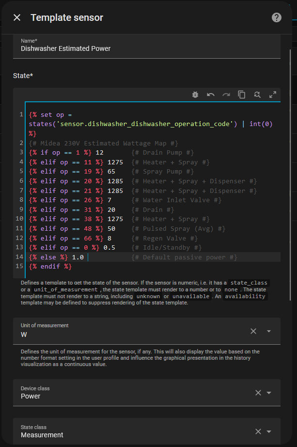
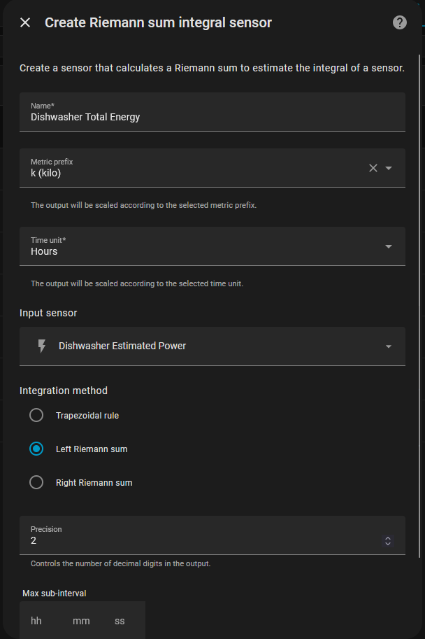
In the end, I created a small home assistant dashboard card to show all the information I want, the code is included in the esphome-midea-dishwasher repo linked above. For a fun test, I created a virtual power sensor using a Home Assistant helper and also added a total energy tracker to test my virtual power monitoring hypotheses. I only ran one cycle so far, but it seems that the energy trackers is on just a little over the real power measured from the energy monitoring plug (0.18 vs 0.19 Kwh for a Rapid program).
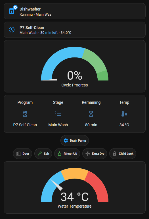
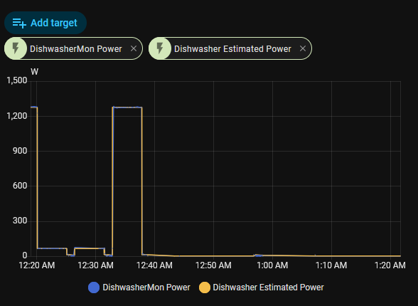
The dishwasher went from a dumb appliance with a 3-digit LED display to something I can monitor from anywhere, build automation around, and track energy usage, it’s possible to estimate power consumption from TX4 states without needing the energy monitor plug. The sniffer sits passively, watching their conversation without either of them knowing.
If the sniffer is positioned in a MITM position, it probably is possible that ESPHome can be used to also trigger actual functions, such as selecting a program and running it, pausing etc (a delay timer is probably done by the front-panel, but that can be done in ESPHome). However, I currently have no intentions to implement active ESPHome components for the dishwasher.