Fun with an oscilloscope, ESP32 DACs and the DVD logo
A few months back I finally bought an oscilloscope, I bought it off a friend that was not really using it anymore (which was evident by the sheer amount of spiders inside the case). It’s a LeCroy 9314L which, I don’t really know the manufacturing date of it (no info plate/sticker), but if to go by the software version date in the EEPROM, it’s from 1995 however software can be updated, the main PCB date-code though is from 1993. It’s a 300MHz 4 channel digital (yes, digital!) scope capable of 10Msp/s and 1Mpt/ch, it should have an effective rate of 10GS/s, however due to some memory issues it cannot reach it’s max sampling rate, crashes here and there and has some auto-calibration issues.
As it can probably be noticed, I’m proud of the scope, and even with it’s drawbacks, I have come to like it as it’s nice and heavy, and most issues even disappear when using it under the 10GS/s rate. Using ke5fx’s excellent 7470A plotter emulator, I can even take screenshots to my PC over serial, and I might in the future make the old scope WiFi capable with an ESP and the serial/GPIB port.
One thing I have not tested/done with my scope is the XY mode. With an old analog scope, when in XY mode, the electron gun is steered directly by the inputs of 2 channels, one channel controlling the X axis and the other the Y axis as opposed to the standard mode which is the X axis is driven by a clock (hence the time axis) and the Y with the input. An example of this kind of operation are when graphing Lissajous curves that can be produced on a XY mode scope, a good explanation of this is in a video by W2AEW. By steering the beam to specific points, a visible trace is left on the phosphors of the CRT and shapes can be drawn out by moving from point to point (as can be seen demonstrated in another video by by W2AEW). I wanted to test this out on my scope, it will not only allow me to confirm that XY mode is working properly, it is also a neat demonstration.
To provide a signal to the scope, I needed a microcontroller with a DAC, I started to go through the dev boards I have and try and find one with enough GPIO pins for an R2R ladder DAC, however, I found an ESP32 dev board that I had bought a while ago for an unrelated project. I was very happy to see that the ESP32 has not just 1, but 2(!) built in DACs, this makes the whole analog generating frontend as easy as 4 lines of code! Even thogh I have has this module for about 2 years, I never actually programmed it, so I had to set up the environment, I went with the Arduino IDE as setting it up was simple as I was on a Windows and I did not need to mess around with python scripts, COM ports and makefiles, just add the espressif repository to the IDE and install the ESP32 tools.
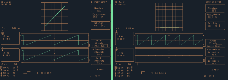
I started off with some simple patters, sweeping the first DAC between 0 and 255. As expected, all I got was a line on the screen, doing this with both DACs gave me a diagonal line, as expected, as the voltage on the first DAC (X axis) increased, the “dot” of the beam moved to the right, and as the second DAC did the same, the line moved up, as voltage steps were the same between the two DACs, the “dot” is moved from bottom left to top right.
#include <driver/dac.h>

void setup() {
  dac_output_enable(DAC_CHANNEL_1);
  dac_output_enable(DAC_CHANNEL_2);
}

void loop() {
  for (byte i = 0; i <= 255; i++) {
    dac_output_voltage(DAC_CHANNEL_1, i);
    dac_output_voltage(DAC_CHANNEL_2, i);
  }
}
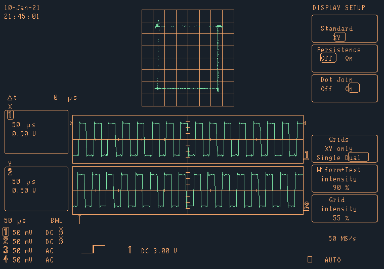
Once I had success with 2 little lines, I went on and tried a square, all I did was to write to each DAC 4 values according to the coordinates of the four corners 10,10,10,245,245,245 and 0,245, the expected result would be a nice square, however, the only the corners were sharp, while the line in between were either faded or non existent, What was going on? The simple answer is that my scope is digital, all the theory of steering the CRTs electron gun was out the window, the scope just takes the values it saw and draws them as dots on the screen, and I have no control over the beam itself, this means there is no streaks of afterglow from the phosphors creating the square, only noise and misaligned DAC signals (that’s the line in the image below). I could turn on the XY persistence and over time the misalignment of the DACs will create a square shape, but that is no fun! It was time for a new strategy. If the scope is going to display the values of the DACs in XY mode as points, I needed to render a point cloud, that is, a 2D point cloud. Doing this is basically telling the scope when to draw a point on the screen, or, a pixel, so it was time for a different setup.
When looking at the images on the scope, the origin point is the center, this works great as long as you pay attention to it, however, to allow for simplification and have a comfortable origin to set my points from, I also changed the scope to DC coupling and added a voltage offset of -1.650v to each of the channels, this is a bit of a cheat, but this makes center of the screen (the original origin point) to be when the DAC is at 1.650v, which is half of the 3.3v VCC voltage, with the setup changed like this, it’s essentially a 256x256 grid of pixels.
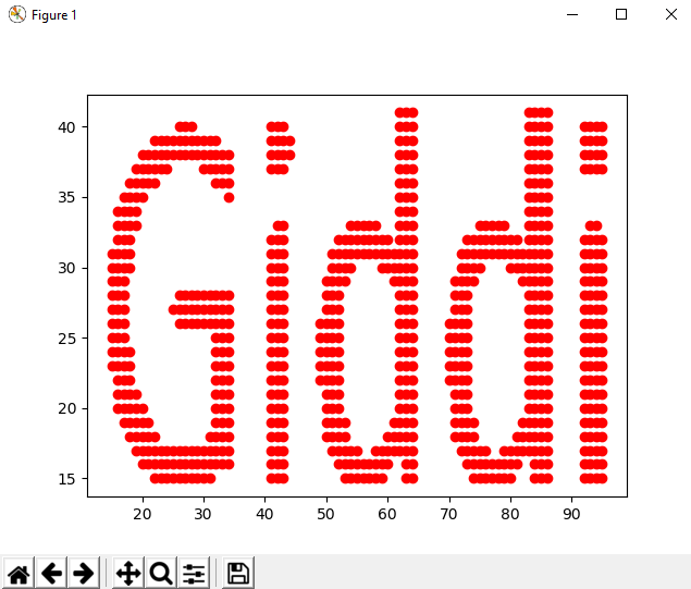
To get the values for each point of the DAC, I wrote a python script that will take in an image and create a C header file to include in the code, I used the Python Imaging Library (PIL) to read in the image, and then convert it to pure black and white, this way, all I had to do is loop over the Image and extract each space where there was a black pixel and save it to an array. Since the origin is the bottom left, and I was already using PIL, I used the transpose method to flip the image top to bottom, so the scope and original image origins matched up. Then all I had to do was to write the values into a C syntax array and some definitions with the size of the array. Once I had this data, All I had to do was to loop over it and write it out to the DACs one element at a time. I also added to the script an option to plot the data with pyplot to preview the points, as the origin of the plot is also bottom left, it was easy as pie.
from PIL import Image
import matplotlib.pyplot as plt
import sys

def  gen_img_arr(img):
	xp, yp = [], []
	img = Image.open(img).convert('1').transpose(Image.FLIP_TOP_BOTTOM)
	for i in  range(img.size[0]):
		for j in  range(img.size[1]):
		if  not img.getpixel((i,j)):
			xp.append(i)
			yp.append(j)
	return (xp, yp)

def  main(argv):
	xa, ya = gen_img_arr(argv[1])
	assert  len(ya) == len(xa), "X and Y are different sizes"
	print("Array size: %d" % len(xa))
	with  open(argv[2], 'w') as hfile:
	hfile.write("#define IMG_ARR_SIZE %d\n" % len(xa))
	hfile.write("#define IMG_MAX_X %d\n" % (255 - max(xa)))
	hfile.write("#define IMG_MAX_Y %d\n" % (255 - max(ya))
	hfile.write("byte xp_arr[IMG_ARR_SIZE] = " + str(xa).replace("[","	{").replace("]", "};\n"))
	hfile.write("byte yp_arr[IMG_ARR_SIZE] = " + str(ya).replace("[","	{").replace("]", "};\n"))
	try:
		if argv[3]:
			plt.plot(xa, ya, 'ro')
			plt.show()
	except:
		pass

if  __name__ == '__main__':
	if  len(sys.argv) < 3:
		print("Usage: %s <input> <output>")
		sys.exit()
	main(sys.argv)
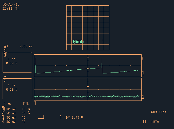
All i had to do now is include the header file the script produced in the code, and then change the loop function to write out the corrdinates to the DACs in a loop. I also added a dacs_out function that just set the each DAC to the desired value. When I was looking at the waveforms with the scope, I set the DACs to 255 on each start of the loop soI could get a nice and simple spike to put my trigger on.
void dacs_out(byte x, byte y) {
  dac_output_voltage(DAC_CHANNEL_1, x);
  dac_output_voltage(DAC_CHANNEL_2, y);
}

void loop() {}
// dacs_out(255, 255);
for (unsigned short p = 0; p <= IMG_ARR_SIZE; p++) {
    dacs_out(xp_arr[p], yp_arr[p]);
  }
}
Since now it’s a point cloud and has a basic coordinate system, it’s is quite simple create transformations, such as sliding the text up/down or side to size. All that has to be done to move the text is to add an offset to the X or Y axis between each drawing of the all the points, a simple for loop.
void loop() {}
// dacs_out(255, 255);
  for (byte offs = 0; offs <= 255; offs++) {}
    for (unsigned short p = 0; p <= IMG_ARR_SIZE; p++) {
        dacs_out(xp_arr[p] + offs, yp_arr[p]);
    }
  }
}
By this time I had proved that the XY mode on the scope works, and this experiment started turning into a bit of a game. I decided it was time to stop and call it a day, but just for a small, last bit of fun, I ended up implementing the bouncing DVD logo. I thought it would be amusing as it’s an iconic animated screensaver, and a bit funny as DVDs players only started coming out in 1997, which is 2-5 years after the scope was manufactured. I first took the DVD logo and shrunk it down to something recognizable but small, I then created the array of points for that image, and then inverted the image and created a second array of points, representing the inverse image. I also added (included in the script above) a line to write out the max point of each array (X and Y) and that’s all I needed.
The animation of the DVD logo is pretty simple, it just moves in a diagonal line at constant velocity, this is done as simply adding 1 to the axis offset variable on each frame loop, then, just as with the scrolling text, adding that offset to the X and Y DAC values. When the logo hits the edge of the screen, meaning the max point value of an axis + the value of the offset is greater or equal to 255, all that needs to be done is to set the direction to the opposite sign to subtract 1 from the offset, making the logo move backwards from it’s current heading. Doing the same (changing signs) when the offset reaches 0 causes the direction to be positive again and start counting up. Another thing I ended up doing is adding a buffer swap when a collision with an edge occurs, changing the buffers of the X and Y coordinates to the inverted image buffers emulates the color change on the original DVD screensaver. The code I used follows after the next image showing it’s operation, but be warned, it is not pretty! (and I had to hack the collision detection size manually to the max logo size or else it kind of glitches).
#include <driver/dac.h>
#include "image_data.h" // Can be found at https://giddi.net/files/image_data.h

// Logo position stuff
byte x_offs = 0;
byte y_offs = 0;
byte x_dir = 1;
byte y_dir = 1;

// Logo params
byte *cur_x_buffer;
byte *cur_y_buffer;
int cur_buffer_size;

// HACK HACK HACK
int cur_max_x = 184;
int cur_max_y = 211;

void setup() {
  dac_output_enable(DAC_CHANNEL_1);
  dac_output_enable(DAC_CHANNEL_2);
  change_buffers();
}

void change_buffers() {
  cur_x_buffer = cur_x_buffer == xp_arr1 ? xp_arr2 : xp_arr1;
  cur_y_buffer = cur_y_buffer == yp_arr1 ? yp_arr2 : yp_arr1;
  cur_buffer_size = cur_buffer_size == IMG1_ARR_SIZE ? IMG2_ARR_SIZE : IMG1_ARR_SIZE;
  // TODO: FIX HACK HACK HACK
  //cur_max_x  = cur_max_x == IMG1_MAX_X ? IMG2_MAX_X : IMG1_MAX_X;
  //cur_max_y = cur_max_y == IMG1_MAX_Y ? IMG2_MAX_Y : IMG1_MAX_Y;
}

void update_positions() {
  y_offs += y_dir;
  x_offs += x_dir;

  if (x_offs >= cur_max_x || x_offs == 0) {
    x_dir = -x_dir;
    change_buffers();
  }

  if (y_offs >= cur_max_y || y_offs == 0) {
    y_dir = -y_dir;
    change_buffers();
  }
}

void dacs_out(byte x, byte y) {
  dac_output_voltage(DAC_CHANNEL_1, x);
  dac_output_voltage(DAC_CHANNEL_2, y);
}

void loop() {
  update_positions();
  for (unsigned short p = 0; p <= cur_buffer_size; p++) {
    dacs_out(cur_x_buffer[p] + x_offs, cur_y_buffer[p] + y_offs);
  }
}
Well, I could of done more, but I really think I should work on something more important, I can’t really see the breakthrough with DACs and point clouds, and no, I will not be implementing an oscilloscope clock or any of that kind of stuff, I was just testing the ESP32 DACs and my scopes XY mode and learning a few things on the way, that’s all. Feel free to roast me about using DC coupling, bad code or whatever…