Format your light bulbs!
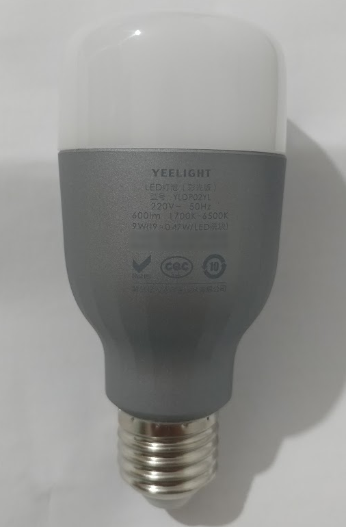
Approximately 2 years ago, I bought a Xiaomi YeeLight bulb (color) for my bedroom. It is one of those IoT smart bulbs that connect to the WiFi and can be controlled with a phone app / Google assistant. I never really used the color features of the bulb, it was always on a warm white setting but it was a convenient way of turning off the lights without needing to get out of the bed to the light switch.
After some 3 years of use (about 5000 - 7000 hours of use) it developed a really annoying flicker, it would turn on as expected, and then after a few minutes it flickers and then stabilizes again, it got extremely irritating so I replaced it with a new bulb. I was going to just throw the bulb away assuming it had reached its end-of-life when I decided to tear it down and see if I could find the reason the bulb failed and also just have a peek inside.
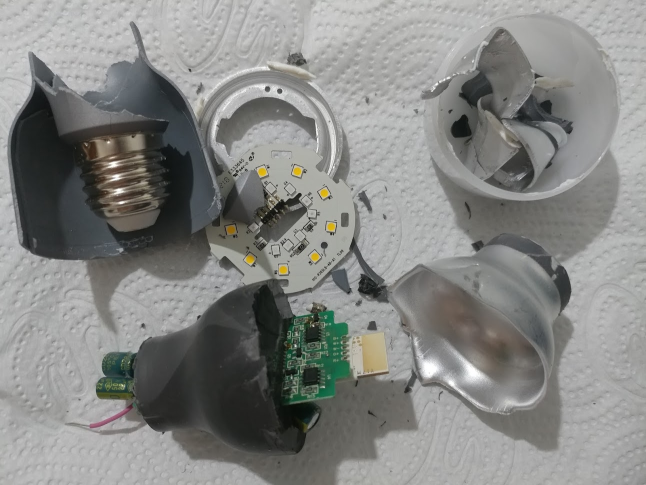
After the bulb sat around for a while (to allow any capacitors to discharge) I started by taking the white plastic cover off the bulb, I found that a twist of the cover with a pair of work gloves with a rubber grip was sufficient to break the glue and crack the bulb open. Immediately I could identify the white LED array (9 chips) with a yellow phosphor coating and an extra 10 smaller LEDs with a white coating conveniently, these were also marked W for white and R,G and B for the color cobs. Protruding out of the middle of the bulb a white PCB piggybacked on a green PCB was visible with a faint outline of a PCB antenna under the white solder mask. Notably, there was a yellowish/brown discoloration of the white solder mask which suggests to me that the PCB in that area was getting really hot. Examining the location and pattern of the discoloration, it seems to be caused by the aluminium backing-plate/heat-sink of the LED chips as it starts where the plate is located near the white PCB and fades away as it gets further away, it also has a noticeable distinct “tan line” where the plastic header connecting the LED backplate to the main PCB was located.
After breaking off the LED backing plate from the protruding PCB, I could see that most of the PCB was buried in some potting compound which was all the way down the neck and in the cap of the bulb. The bulb shell was made out of two layers, plastic on the outside and aluminium on the inside. A Pair of cutters broke the plastic out shell off quickly, but the aluminium shell was tough and I ended up peeling it bit by bit. At some point, I had enough grip to grab the potted unit and tear it from the rest of the neck and the cap, breaking the wires for the main electricity and an inline fuse located in the cap.
Getting the potting compound off the PCB was not as hard as I expected. I don’t know if it was the type of material or a result of the heat from hours of work, but it was easy to slice into and rip apart, most of the potting compound peeled off in big chunks, but some of it crumbled like dry rubber, it released pretty easily from the PCB but I had to use some tools and picks to get it out from under and in-between some through-hole components (capacitors, transistors an inductor and transformer). Finally, I had the full PCB in hand.
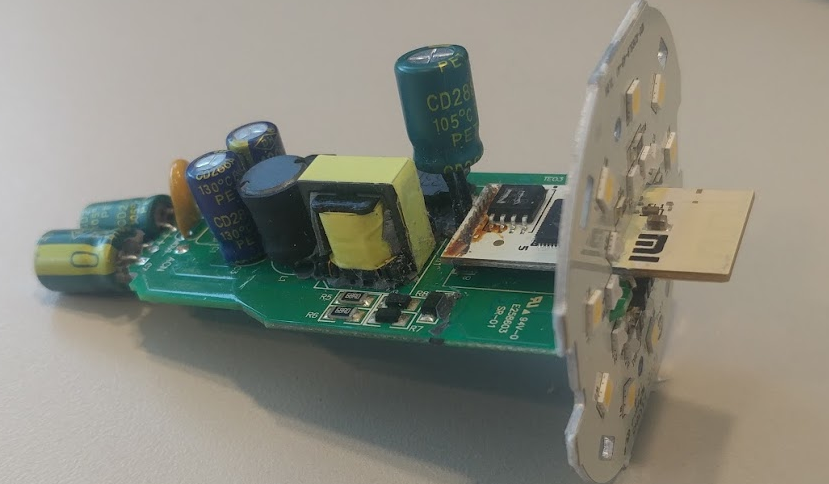
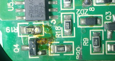
At first glance the PCB looked fine. The header connecting the main power PCB from the control module (the white PCB) was crummy and horrible, but that could be old flux left from a hand-soldering job of the module. The top of the board seems almost mirrored, two Fairchild NDS9948 MOSFETs used to drive the various LEDS. On the side of the white LEDs there was a clue to what might be going on. Most of the joins on the board were of a low-profile with a matt-grey look and a distinct wicking pattern on the pads, however two or three of these connections on an adjacent resistor and transistor were ball shaped, shiny and had some crud around them, maybe this is the problem? Either the traces/components got so hot they melted the solder, which might have caused an intermittent connection of the white LED driver, or it was a bodge job done after the original soldering, either way, I did not like the look of those solder joints. Other than that there were no other visible clues to why the bulb failed, I even desoldered most of the components of the suspected white LED driver, but none of them seemed to be faulty when tested out of circuit.
I am no electrical engineer, so unfortunately the mystery of the failing bulb continues to haunt me, however something else caught my attention while disassembling the bulb, it was that white PCB “smart” module which controls the main board. It’s a very simple board, a GigaDevice 25Q16 serial flash chip and a Marvell 88MW300 WLAN microcontroller (beside a crystal and some passives). The first thing going through my head was “Hey! They did not use an ESP8266!” the second was:
Wait a sec! I was going to throw this away. What are the chances my SSID and PSK are unencrypted in the flash chip, free for all to find?
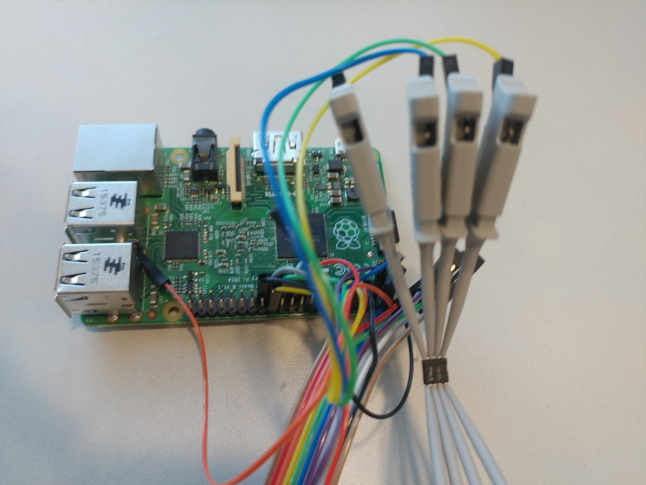
That’s when I knew I could not just throw the bulb away, I had to get to the flash chip and find what’s stored inside it. After a quick desoldering, I decided to up the flash chip to a [Raspberry-Pi] (Version 2 Model B)(https://en.wikipedia.org/wiki/Raspberry_Pi) and read out the flash contents. To hook up the device to the Pi, I first flashed a micro-SD card with Raspberry Pi OS and then changed the config.txt file in the boot partition to enable the SPI bus and UART, this is done by adding uart_enable=1 and dtparam=spi=on at the end of the file. After that, I connected a USB<->Serial adapter between my computer and the Pi (SSH can be used too, but I could not be bothered) and the flash chip was hooked up using some grabby probe clips to the Pi:
USB<->Serial (Pi<->PC) adapter hookup:
| Adapter Pin | Raspberry Pi Pin |
|---|---|
| GND | Ground (6) |
| Rx | TxD (8) |
| Tx | RxD (10) |
25Q16 Hookup (Chip<->Pi):
| Chip Pin | Raspberry Pi Pin |
|---|---|
| CS# (1) | CE0 (24) |
| SO (2) | MISO (21) |
| WP# (3) | 3.3v (17) |
| VSS (4) | Ground (25) |
| SI (5) | MOSI (19) |
| SCLK (6) | SCLK (23) |
| HOLD# (7) | 3.3v (17) |
| VCC (8) | 3.3v (17) |
Once the Pi was booted, I logged in and listed all the SPI devices, this is to check the SPI bus on the Pi is enabed and the kernel has loaded the needed modules, after that is was just a case of using flashrom to identify the chip to make sure communication is good, then, just read out the flash and save it to a file.
pi@raspberrypi:~$ ls -lash /dev/spi*
0 crw-rw---- 1 root spi 153, 0 Mar 17  12:46 /dev/spidev0.0
0 crw-rw---- 1 root spi 153, 1 Mar 17  12:46 /dev/spidev0.1

pi@raspberrypi:~$ sudo flashrom -p linux_spi:dev=/dev/spidev0.0,spispeed=1000
flashrom on Linux 5.4.83-v7+ (armv7l)
flashrom is free software, get the source code at https://flashrom.org

Using clock_gettime for delay loops (clk_id: 1, resolution: 1ns).
Found GigaDevice flash chip "GD25Q16(B)" (2048 kB, SPI) on linux_spi.
No operations were specified.

pi@raspberrypi:~$ sudo flashrom -p linux_spi:dev=/dev/spidev0.0,spispeed=1000 --read bulb_flash.bin
flashrom on Linux 5.4.83-v7+ (armv7l)
flashrom is free software, get the source code at https://flashrom.org

Using clock_gettime for delay loops (clk_id: 1, resolution: 1ns).
Found GigaDevice flash chip "GD25Q16(B)" (2048 kB, SPI) on linux_spi.
Reading flash... done.
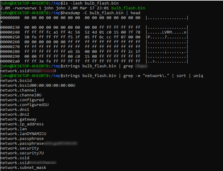
The first thing I did once I had the firmware in hand, was to grep for my SSID, sure enough it appears plain text in the flash dump, this is not a problem, as anyone can sniff and find my SSID (as it’s not a hidden network). I noticed the SSID was prefixed with the text network.ssid which is probably a configuration entry identifier, grepping for network. (grep -e “network\.” /tmp/bulb_flash.bin) reveals more network configuration entries including a field named network.passphrase, and as expected it had my WLANs PSK in plaintext. A quick sort of the fields reveals there are 3 WLAN configuration slots, with 6 fields and an extra 2 configuration slots for IP settings:
| Field Name | Observed Value | Notes |
|---|---|---|
| network.bssid | 00:00:00:00:00:00 | Runtime filed? |
| network.ssid | xxx | Contains my SSID |
| network.channel | 0 | Runtime filed? |
| network.security | 7 | Security type enum? |
| network.passphrase | xxx | Contains my WLAN PSK in plaintext |
| network.configured | 1 | Indicates the slot is used |
I am not sure of why there are 2 slots for IP settings and 3 for WLAN credentials, but if the image is anything like other OTA firmwares such as for the ESP8266, there might be 2 copies of the firmware (running and backup) which explains the 2 IP settings copies (but not the odd 3 WLAN settings fields), I’ll try and look into that when reversing the firmware (if ever). Since the bulb is in pieces and half desoldered, I was not able to see what will happen if I connect the bulb to a new network, will it overwrite the current SSID and PSK? or just add it in a different slot, saving the old and the new. The main lesson to take away from this so far is Do NOT throw away smart light bulbs without destroying/wiping the flash chip, unless you want people be able to find your SSID and PSK.
I’ll end my post here, as all that I wanted to know was why is stopped working, I didn’t even plan on writing a post about it, But since have a full firmware dump, I might reverse engineer it in the future just to see how it operates, however it’s unlikely.