Replacing a Roborock Ultra dock PSU (Error 35)
Background
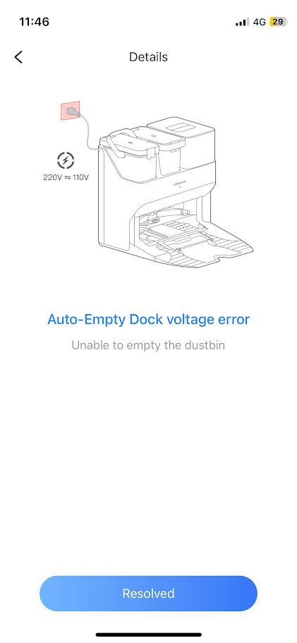
Almost two years ago, I purchased the Roborock S7 MaxV Ultra, a vacuum and mopping robot with an “Ultra” docking station for filling its moping water tank, cleaning the mop, and emptying the dustbin into a larger bag. For almost two years, both the robot and dock functioned flawlessly, with no issues. However, two months ago, a notification on my phone disrupted the routine - “Error 35: Auto empty Dock voltage error.” Upon manually running the dustbin emptying cycle, everything seemed fine. Two weeks later, the same error surfaced, but this time during the cleaning cycle, the robot declared loudly to the room “Voltage error, cannot empty dustbin.” The app indicated a power issue with the dock, even though the robot’s mop routine worked seamlessly just moments before, the problem seemed confined to the dock vacuum.
Pinpointing the Issue
My first attempt was a simple power cycle by unplugging the dock, suspecting a firmware bug, but that provided no resolution. The app continued to suggest a mismatched voltage in the outlet, which did not make sense since the dock had been working for almost two years. Online searches proved futile, with no relevant information from official Roborock forums. The error seemed uncharted territory with no solutions, only questions on Reddit, and most often the solution was to make a warranty claim or assumptions about voltage differences between countries, which did not apply to my situation since I got the unit in my country.
To diagnose the problem, I considered the following:
- Dock functions, except for dustbin emptying, were operational (mop, charge).
- The app error pointed towards an issue with the mains voltage input.
Using a multimeter, I measured the wall socket voltage, finding it at the nominal 230v for my location, ruling out overvoltage or brownout. Replacing the power lead, thinking maybe it was faulty under load yielded no improvement. To investigate further, I decided to open the back of the unit, searching for loose wires. Though nothing seemed amiss, however, it did add another point for consideration, that the vacuum motor used mains voltage directly from the PSU.
The cause still remained unclear. Given that the vacuum motor’s high voltage was controlled by the PSU, I speculated that a power spike might have damaged a voltage sensor, a relay or a power MOSFET had burned out. Despite encountering power spikes in the past without impacting appliances, I decided to explore the PSU for potential issues. Unfortunately, the unit was sealed, since I could not find another explanation for the cause other than the PSU misbehaving, it prompted me to opt for a PSU replacement unit, hopeful it was some sensor or component in that sealed box that got damaged by a power spike. I ordered a new PSU and got to replacing it.
Since I did not find any information about this topic, I decided to write a step by step guide to the process, if anyone needs to do the same.
Note: Since I write my posts with a long delay, I found that between the time of writing this and publishing dome did actually write about replacing the PSU on one of thee units on reddit.
Also, in the teardown, you will see there is a small board, the “motherboard” of the dock. the microcontroller on it is Nation Tech STM clone as far as I can tell, and yes, I did try to connect to the micro-USB connector hoping to dump the flash but did not see anything happen in dmsg and decided to not make my problems worse by bricking or erasing my docks firmware.
Step-by-step PSU replacement guide
This will void your Roborock warranty! And on that note, this guide is without warranty; proceed at your own risk. No, I did not clean the dock before working on it; yes, it is dirty and needs a clean.
Tools needed:
- Phillips #0 screwdriver
- Phillips #2 screwdriver
- Shoebox
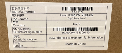
- Replacement PSU, this was the exact item I ordered.
First, remove the robot from the dock, the water tanks and the vacuum bag and cover from the top of the dock. Unplug the dock and remove the power cable. Also, remove the small ramp in front of the dock by gently lifting it upwards. You might want to move the dock to a table in a well-lit area (I covered my work area with some plastic in case any water got out).
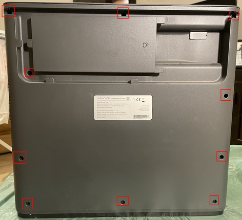
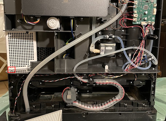
Start by removing the 10 PH2 screws (red in the image below) located at the back of the unit (one of the screws is covered with a warranty sticker, not pictured).
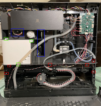
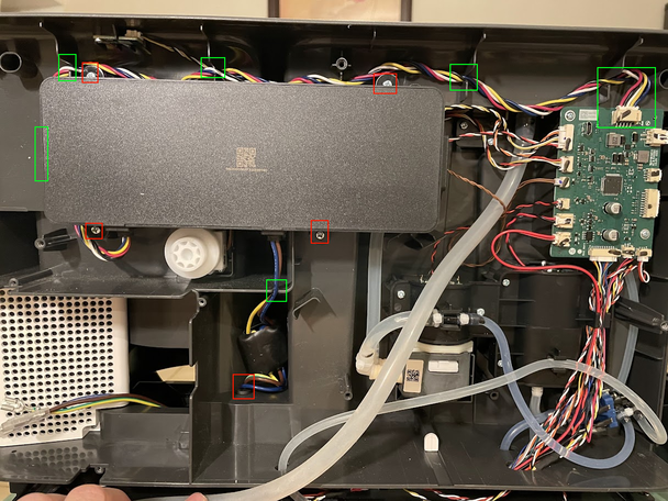
Once the back cover is off, the top of the unit needs to be separated from the bottom. The top is held down by 9 screws. Start by removing the 6 visible screws (red in the image below). The right and left-most bottom screws hold on the side panels, which each hide an additional screw on the side. The panels slide out towards the back and then can be lifted off once the retaining screws are removed. Another screw is located behind the vacuum air redirection shield. The shield can be removed using three screws (green in the image below), and the wastewater hose must be moved to the side to access the shield’s bottom screw. In the image below, the blue markings are the PSU cables that run to the board and the vacuum motor.
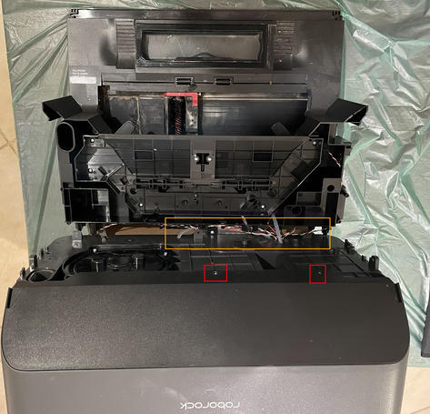
Once all screws are removed, the top can be lifted off easily (don’t force it! Check for missed screws). Some might want to remove the hoses and cables, but I found that the hoses have enough stretch, and the wires have enough slack that a shoebox behind the dock can be used to support the top, and the top part can be hinged open, taking care not to stretch the wires and hoses too far (note the orange area in the image below). Once the top is removed, a front cover needs to be removed by removing two PH0 screws and unclipping it from the dock (red in the image below).
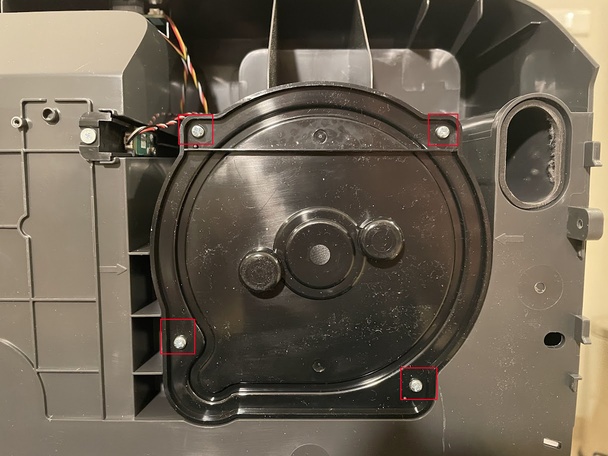
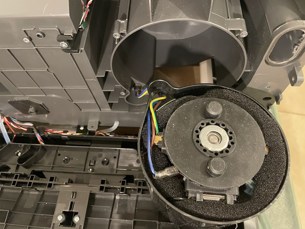
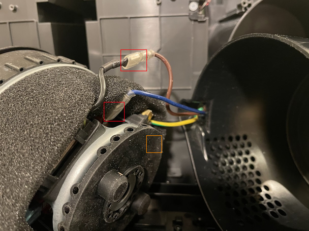
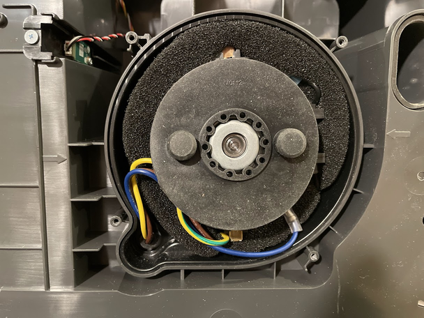
Once the front cover is removed, the vacuum motor cover is visible and can be removed to access the motor and to remove the wires, remove the 4 screws (red in the image below). There is a white gasket on the vacuum cover, so make sure not to lose it. Once the cover is off, the motor slides out with a plastic shield. Remove the motor from the shield to gain access to the connectors of the wires. To remove the connector, push on the clear rubber part, as there is a locking spring in the connector that holds the connector in place. One of the connectors (ground) does not have a clear cover and is buried inside the foam surrounding the motor; there is no need to remove the foam, just pull it apart from the motor near the ground connector and disconnect the wire (connectors in red in the third image below, one hidden connector in orange). The motor has two rubber caps on each end; if they fall off, just place them back into place.
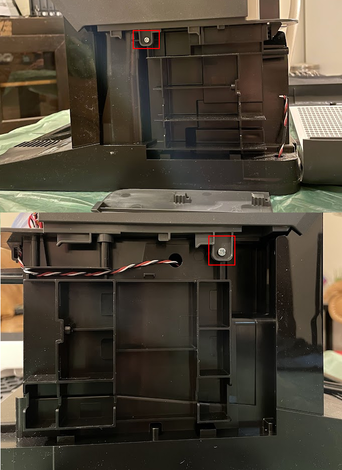
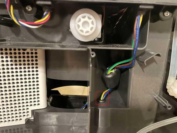
Once the connectors are disconnected from the motor, the top part needs to be placed back on the unit, and the wires need to be pulled out from the back; the wires pass through a hole and a rubber grommet to the motor area (red in the image below). When replacing the top part of the unit, be careful not to catch and damage any of the fine wires in the back.
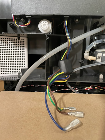
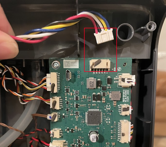
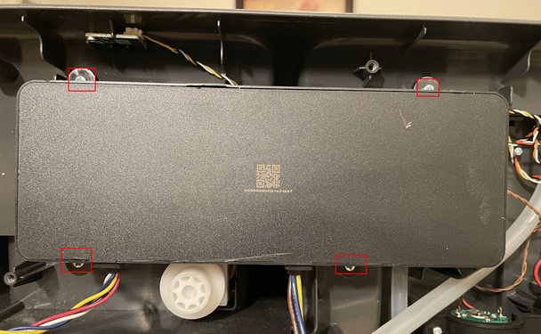
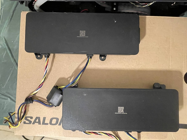
Now it’s time to remove the PSU. Start by carefully disconnecting the connector on the top of the main board (upper right of the back). Do this gently to not rip the connector off the board (red in the image below). Once the connector is disconnected, remove the wires from the retaining slots up to the PSU. Once the wires are removed, the PSU can be removed using 4 PH2 screws (red in the second image below).
Once the PSU is removed, install the new PSU by screwing in the 4 screws that were removed in the previous step and reroute the wires to the main board and place the new wires and grommet into the hole to feed the wires to the motor (green in the image below are slots for the wires, red are screws and grommet).
Once again, hinge open the dock and connect the wires back to the motor, make sure to connect them in the same order they were connected previously. Once connected, tidy up the foam and repack the motor back into its housing and replace the motor cover. The brown is tucked between the plastic housing and the foam; it will be visible from the back when closing up (see image below).
Once completed, all disassembly steps can be taken in reverse to put the device back together. Take note that no hoses have disconnected by mistake while working on the device:
- Attach the motor cover and secure it with screws.
- Attach the front cover plate and secure it with clips and screws (PH0).
- Place the top of the unit back on the bottom (without pinching wires).
- Secure screws (side screws, back screws, and the hidden screw behind the air shield).
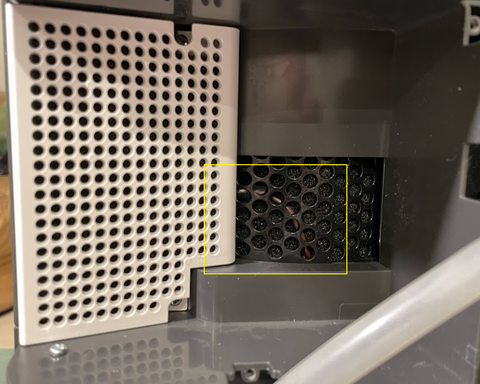
- Place the air shield back into place (see the image below; you should see the brown wire from the motor in the mesh).
- Place all hoses and wires into place.
- Close up the unit.
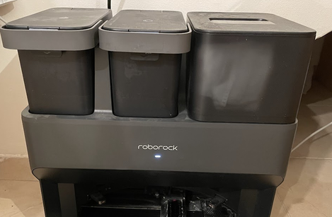
Once all is done, connect the unit to power and see that the indicator light turns on. Reinstall the tanks, bag, and cover, and don’t forget the ramp. Once done, the robot should be able to dock and start charging. In my case, the robot also decided to empty the dustbin immediately, which gave me an indication that the operation was a success, but if it didn’t, I would’ve started it manually. I also did a mop wash cycle to check that all functions were in working order.
Overall, apart from the power supply being a bit sensitive, I found the dock is user-serviceable and comes apart nicely. It was not such a bad job after all, I also decided to add a surge protector to the dock to attempt to safeguard it from any voltage spikes that may occur in the future.