Commercial pulse oximeter teardown
In the past few days, I have been playing around with some hobby pulse sensors (pulsesensor.com) and ECG (AD8232) modules. I remembered I got a finger clip pulse-oximeter a while back that was too broken to use (broken - physically, glued back together). I decided to take the pulse oximeter apart and take a look at how it’s constructed and what makes it tick. The first thing I did was to break apart the case and free the small PCB inside, as this was a finger clamp, I did have to battle with some sharp springs (that now are somewhere on the floor) and use a pair of pliers to rip the small photo-sensor that was well glued into the case.
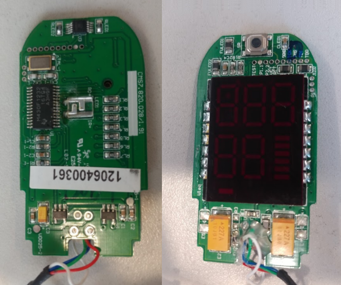
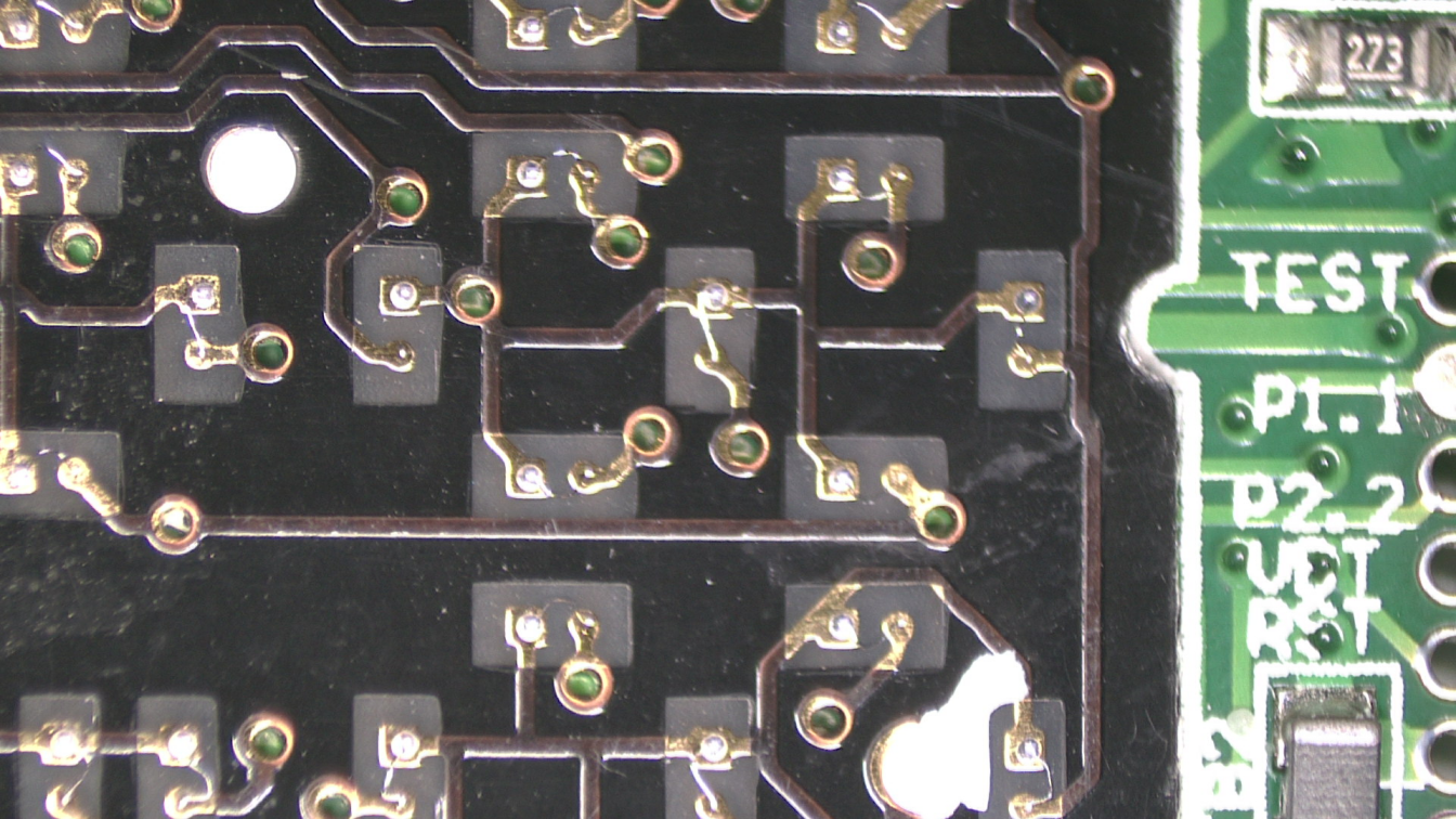
On the one side of the board, the device has a single TI MSP430F1232 microprocessor, a crystal (8 MHz), what appears to be as a high powered LED, and a SPDT (single pole double throw) CMOS switch (labeled SGM3005). On the other side of the board there is only a button, and a daughter board with some LED 7-segment displays and LED bars. The first thing I did was to take the plastic cover off the display module and look at the board. I was not disappointed! I was expecting the display module to have a bunch of small LED packages, instead the module had lots of tiny pads, and the LEDs were bare and attached to these pads with tiny bond wires. I found that to be really interesting, and under a microscope it looks even cooler. The tracks on looking at the number of segments on the display, and the number of connection to the board, it seems there is some multiplexing going on to drive the segments as needed, saving on IO pins. In order to appreciate the bare LED dies, I applies a small voltage to some of them and watched them glow under the microscope.
Now, as I mentioned above, I did play with some pulse sensors and after using the oximeter and the sensors, I wondered why did the oximeter use a red LED to measure the pulse and oxygen saturation and not a green LEDs which are common in smart watches, fitness bracelets and more? After soe reading up on the subject, I found the answer. Turns out, green light is well absorbed by the human body, by using this green light, the noise floor from external light sources (ambient sources) is reduced and making it easier to detect light return changes and thus a pulse rate. Unfortunately, the use of green light also reduces accuracy, since the green light is well absorbed, the sensor can only takes measurements off the surface of the skin. By using red light (as the case in the oximeter) the light penetrates much deeper into the body and allows to collect information from multiple tissue beds.
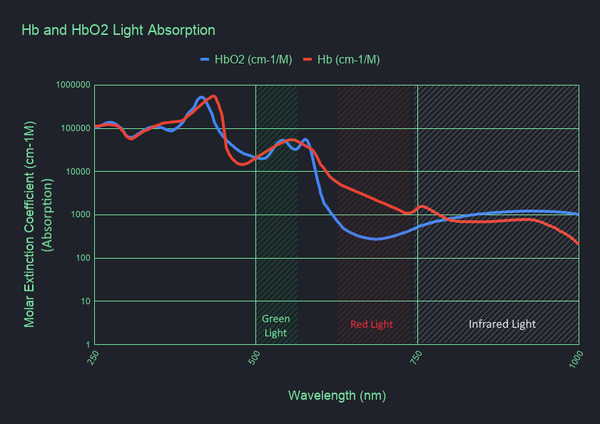
Another interesting thing I learned about the oximeter is that a single light source is not enough to detect oxygen saturation. In order to be able to measure the oxygen saturation, a second light source is needed that has different absorption characteristics than the red light, and by cross referencing the two measurements, a oxygen saturation level can be computed. In the case of the oximeters, a IR (Infrared) light source is used as the second reference as it has an opposite absorption curve in hemoglobin than the red light. How exactly is this used? when no oxygen is present in the hemoglobin (deoxygenated, Hb), the red light is absorbed while the IR is not, but, when oxygen is present in the hemoglobin (oxygenated, HbO2) the IR light is more absorbed than the red light. Using a photocell and detecting these absorptions rates, a simple result can be calculated to tell if the hemoglobin is oxygenated, and with a bit more logic, a value of the amount of oxygen present can be calculated and presented as the % of O2 in the blood. The following graph describes the absorption characteristics of different wavelengths for oxygenated and deoxygenated hemoglobin (note the “flip” between the red and infrared absorptions).
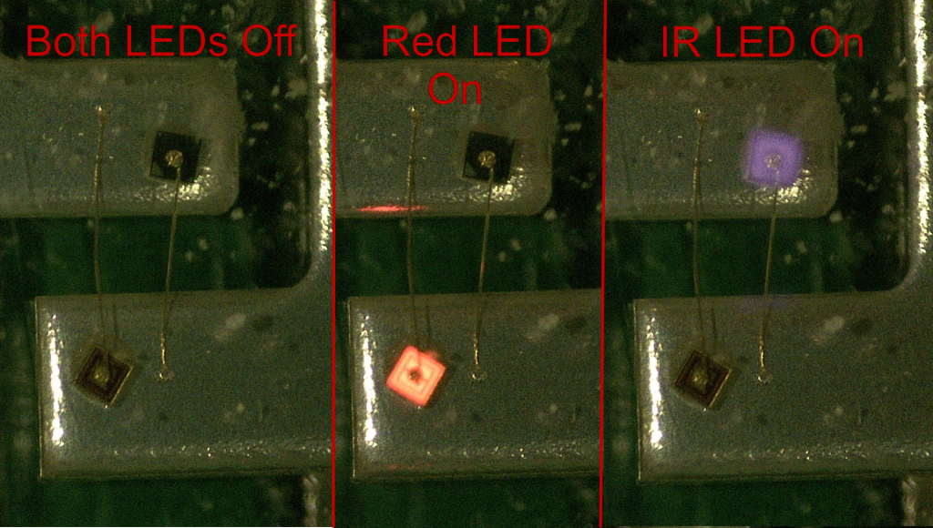
So where is this infrared LED? there is only one LED package on the PCB. Well, it’s in the same package! Looking at the clear LED package under the microscope, 2 dies a visible, one has a reddish tint to it, and the other is black. The dies are placed back-to-back, each terminal of the LED package acts as a anode and cathode depending on the polarity, and since LEDs are diodes, there is no short between them when reversing polarity. Odiously there is a breakdown voltage, but as long as the voltage is regulated this is no problem. This also explained the CMOS SPDT switch, this SPDT switch is used by the MCU as the switching component for the anode and cathode of the package, by rapidly switching the CMOS, the LED package polarity is switched and the package emits a pulse of red light, then switches and emits a infrared pulse and it cycles on and on and on. Each time MCU is changing the polarity of the LED package, it trying to detect a different wavelength. I hooked up the package to a PSU and took a photo of the lit die, I then switched the polarity and took another image, infrared may not be visible to the human eye, but for the camera taking the photos, it looks like a faint purplish glow.
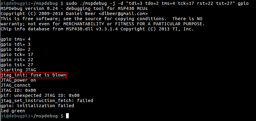
In my next step of the teardown, I wanted to extract the code from the MSP430 and reverse engineer it to see the algorithm used to calculate the pulse and oxygen saturation. Unfortunately, this failed. I started with hooking up wires the the JTAG debug pads on the PCB, I then used a Raspberry Pi to try and read out the memory from the MCU, but the manufacture blew the security fuse, disabling the JTAG port.
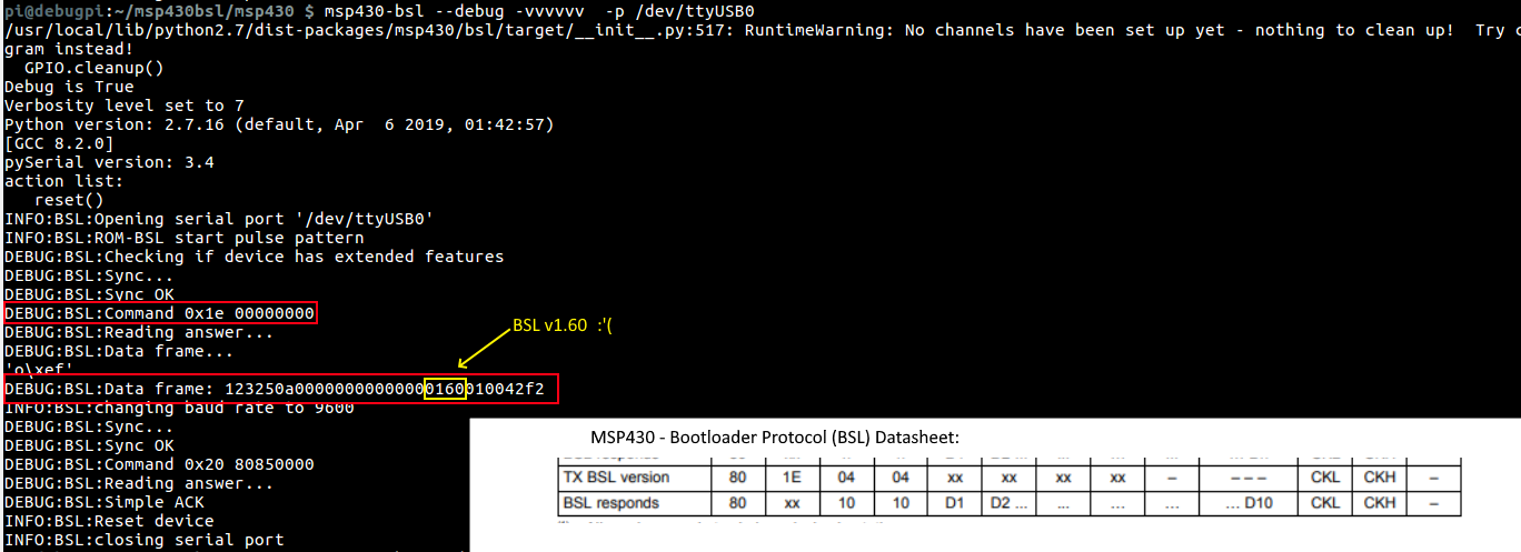
I then tried to connect to the BSL interface and check which version of BSL it was running. In a paper by Travis Goodspeedn, Travis shows a method of cracking the BSL password due to unbalanced timing in the password check. I connected up the wires again to the Raspberry Pi and ran a software BSL program to query the version of the BSL, it came back as BSL version 1.60, unfortunately, this version does not contain the vulnerability presented by Travis, the only sane method for extracting the firmware is to brute force the password which is generated by the compiler, not user set and is 256 bits in length, and according to previous research, brute forcing the password can take from 32 to 128 years, and that is if it does not have the automatic flash erase turned on. There is still hope though, In a different presentation built on Travis’s work a method of glitching the JTAG port was presented by flashing the semiconductor with a camera flash, discombobulating the chip into granting JTAG access, this requires to do dome chip de-encapsulation, which is not something I can get done easily.
In conclusion, maybe I’ll one day manage to de-encapsulate the chip, or even glitch it with a chip-whisperer or similar. For now, the process of learning how these types of pulse-oximeters work was very interesting and taught me much. Until the nxt time, have a nice day.