A look inside a digital pregnancy test
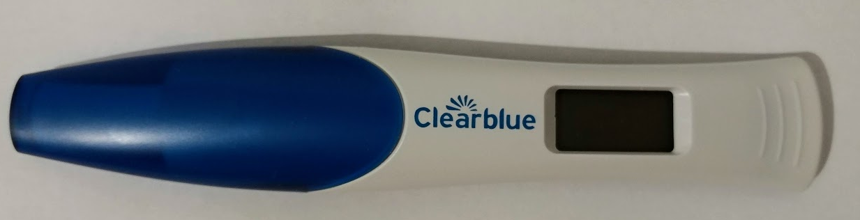
While searching my local pharmacy shelves for a product, I came across some pregnancy tests, I normally don’t really pay attention to this kind of stuff since, as a boy, I don’t thing I can get pregnant. However, one of the tests on the shelf said it can not only detect a pregnancy, but indicate the pregnancy week to, then, I noticed it was a digital test, not a simple color changing stripe type, so I picked one up to see how it works. The device is a “ClearBlue pregnancy test with weeks indicator”. Taking the device out of the box and wrapping, it has a outer plastic shell with a cap on one end with fibrous hard-sponge stick thing to pee on. In the middle of the plastic shell there was a small window with an LCD screen.
Taking the outer casing off is pretty easy, it is only clipped into place with some plastic tabs. As soon as I got the plastic shell so off, I could see 3 things. The first were two test strips, one with a faint blue smudge, and the other with a much darker shade of blue. The second thing I noticed were some test-pads on the PCB, and the third, was a COB blob. The board was still partially covered by a plastic shroud, however the when I saw the COB it really made me sad, as far as I know, I will not really have any way to identify the chip inside, any even if it’s not a custom IC, chances for dumping/flashing/debugging the processor are slim to none.
On the other side of the board, there was only the LCD module, in the plastic shroud there was a pill shaped thing and two contacts going out to the urine sampling stick. The pill looking thing was located right under the urine sampling stick-sponge, from it’s position in the device (where the opening for the urine sampling stick is) and believing the manufacturer did not hide candy/contraception pills inside it’s devices, it is safe to assume this pill is some desiccant to prevent ingress of moisture that can either effect the readings or the electrical components. The contacts, are probably there as a switch, which when soaked in urine, triggers the tester to wake up and do it’s job.
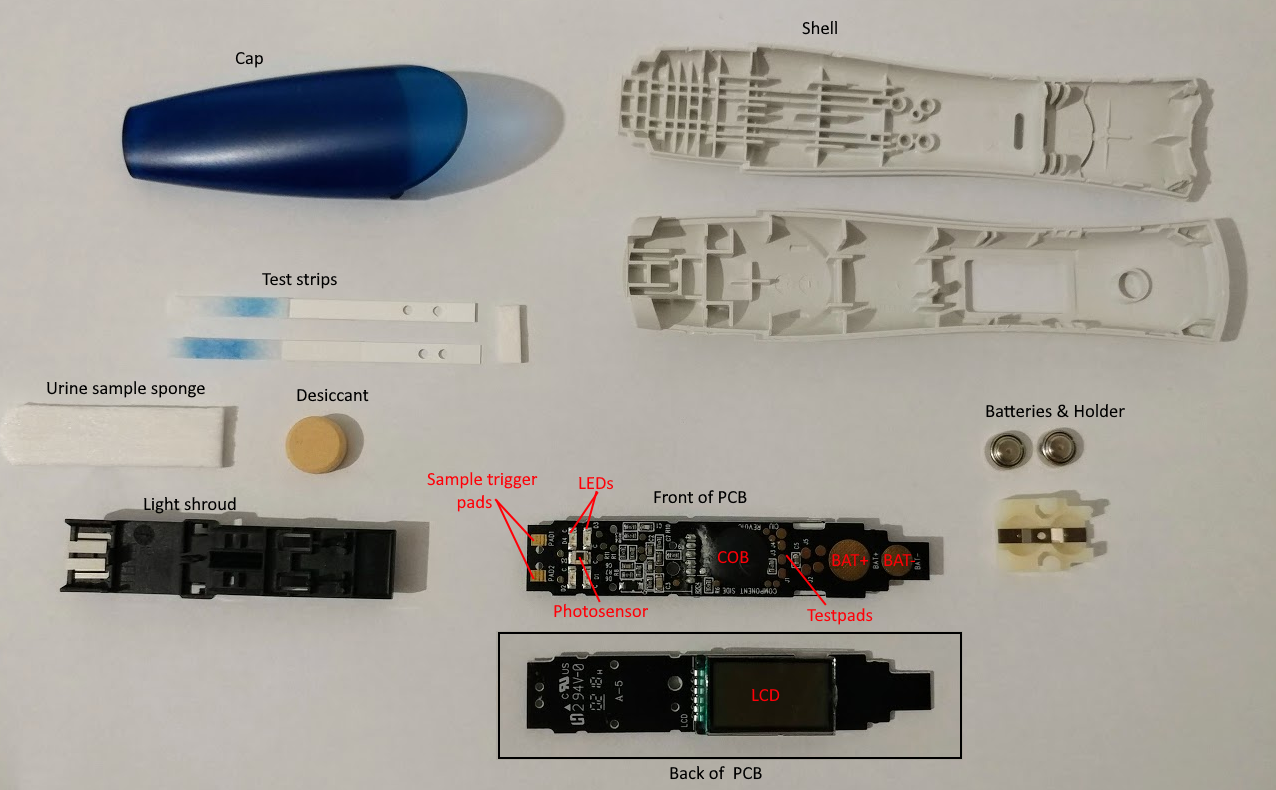
Using a knife, I cut off the sonic welds that kept the plastic shroud in place, and reveled the full PCB. Mostly a bunch of passive components (resistors/capacitors) but also, what looked like 4 LEDs and a single photosensor in the middle. Examining the plastic shroud, reveals that for each LED on the board, there is an opening to shine through and up onto the test strips, 2 LEDS spaced apart a few millimeters for each test strip. There is a piece of plastic in the shroud that blocks direct light from the LED shining onto the photosensor, which means the photosensor is measuring the light reflected by the strips. Assuming by the color smudges on the strips they are supposed to create a blue line when activated, this means more light will be absorbed by the strip in the line area, resulting in the photosensor reading a lower reflected light level.
With this information, the basic operation of the device is mostly revealed, but first, we must understand how pregnancy test work. The test strip, also known as a sandwich lateral flow immunochromatographic assay is a strip made out of a wicking material, on the one end of the strip mobile (free floating) antibodies with colored markers are placed which can bind with hCG hormones that are produced at pregnancy. Further up the strip two more sets of antibodies are placed but this time immobilized in place. When urine is placed on the one end of the strip, the hCG hormones in it bind with the marker antibodies and the capillarity action of the strip washes them up stream passing them over the next group of immobilized antibodies. This group will cause them bind to them on if they are carrying the hCG hormone, producing a neat stripe of color on the strip. The excess mobile antibodies which did not bind with hCG continue up the to the next group of antibodies and cause a second color change which indicates that the antibodies got carried up all the way and that the test was completed, hence, 1 stripe indicates a successful test, and 2 stripes indicate a larger than normal presence of hCG hormone, meaning pregnancy.
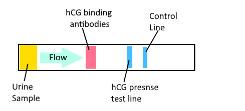
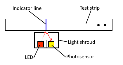
With a standard, non digital pregnancy test, this is what the viewing window for the test strip shows, it’s blank at first, when the urine sample stick is soaked, it will wick the liquid onto the strip and cause a the color change, giving the classic 2-line for-pregnant result and 1 for no. In the case of the pregnancy test I took apart, to determine a pregnancy, the device uses it’s LED and photosensor to detect a color change on the test strip, assuming one LED is for the control and the other is the indicator, we can understand why there are 2 LEDS for each strip. However, the remaining question is how does it determine the precise pregnancy week (from 1-2, 2-3 or 3+)?. Looking at the instructions, they explain that their tests are super sensitive and can detect 25mlU/ml, and I can only guess that it does an “analog read” of the reflected light to determine the week as more time passed since conception, the increase in hCG hormone yields a darker line, at some point (3+ weeks) the line gets saturated and can no longer indicate properly the time frame.

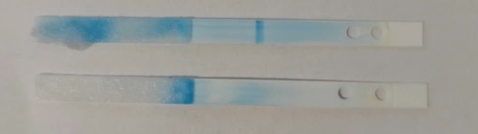
I wanted to test the device (with water) and see what result came up, however after I replaced the battery cells, I found the LCD flashing with all segments displayed, it sees that when the batteries were removed, it put itself into some locked state and will not let me continue with the test. This can be some anti tampering mechanism, but I suspect this is more to keep the manufactures profit margins in check and prevent users from replacing the test strips and resetting the device. I will try and see if maybe grounding/switching one of the test pads will get it to work again. For now, to see the strips in action I dipped them into a drop of tap water. The strips immediately started to wet and capillary action commenced!. After a minute, a clear blue line appeared on one of the strips, this as expected is the control line. An interesting thing I noticed was the lack of a control line on the second strip, I would assume you would make sure that both strips are active and valid, I guess if the control line appeared on the one, then both strips got soaked properly.
For an impulsive buy while at the pharmacy, this was definitely interesting, it’s was interesting to learn about lateral flow tests and see how these digital pregnancy tests did not really introduce any new technique, just simplified the user interface to determine positive or negative pregnancy. I was a bit bummed that it used a COB and was not able to take look at the code that does the actual measuring from the photosensor, but I will continue to try and see if I can get anything out of it. If you have any info on the testpads/COB, please feel free to contact me or leave a comment.
Update - 27/11/2020
I had a more in depth look at the traces located around the LEDs and the photosensor. I located two testpads next to the photosensor that were connected to it’s terminals, I also figured out how the device fires each LED in sequence. Just like with the Pulse Oximeter teardown I did, the LEDs are using a back-to-back configuration in 2 groups of 2, connected on one side to a common trace, meaning 3 traces are used to select and switch on a single LED at a time. After playing around with a multimeter testing the photosensor, I decided to connect the photosensor up to my oscilloscope and drive the LEDs in sequence as the device would do under normal operation. I soldered wires on to some convenient testpads they left around and two the two traces from each 2-LED group, I added a 180 Ohm resistor to do some current limiting. I then wrote a small program on a RaspberryPi to drive the LEDs in sequence, 250ms on for each LED and 2 seconds of between cycles. I also added two wires to the photosensor, and connected the oscilloscope probe to them.

// LED driver source
// Compile with: gcc -Wall pregtest.c -o pregtest -lwiringPi
#include <stdlib.h>
#include <signal.h>
#include <wiringPi.h>

#define PIN_COMMON 0
#define PIN_GROUP1 1
#define PIN_GROUP2 2
#define STEP_DELAY 250
#define CYCLE_DELAY 2000

void doState(int common, int group1, int group2, int sleep) {
        digitalWrite(PIN_COMMON, common);
        digitalWrite(PIN_GROUP1, group1);
        digitalWrite(PIN_GROUP2, group2);
        if (sleep)
                delay(sleep);
}

void sigintHandler(int var) {
        doState(0, 0, 0, 0);
        exit(0);
}

int main(int argc, char **argv) {
        signal(SIGINT, sigintHandler);
        wiringPiSetup();
        pinMode(PIN_COMMON, OUTPUT);
        pinMode(PIN_GROUP1, OUTPUT);
        pinMode(PIN_GROUP2, OUTPUT);

        for(;;) {
                doState(1, 1, 0, STEP_DELAY);
                doState(0, 0, 1, STEP_DELAY);
                doState(0, 1, 0, STEP_DELAY);
                doState(1, 0, 1, STEP_DELAY);

                doState(0, 0, 0, CYCLE_DELAY);

        }
}
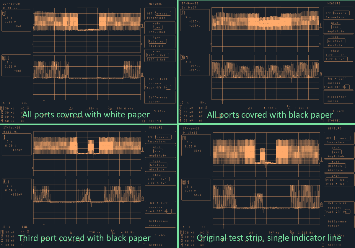
After working out the HIGH/LOW combination for each wire to select each LED, I put the plastic shroud back onto the PCB and started taking measurements. On the shroud, there are 4 ports which allow the LEDs light to shine through and reflect off the test strip. An interesting side-effect I noticed while looking at the traces was I could see a 50Hz wave, checking the photosensor with a battery (DC) powered flashlight did not produce this 50Hz signal, only when connected to the RaspberryPi. I took a closer look at the wave, and it had a typical capacitor curve to it. The interesting thing was that this noise was there even when the LEDs were powered off, which means it’s not a result of some PWM on the GPIO pins. As i’m not an electrical engineer, and especially don’t have expertise in the low signal noise fields, I just assumed this was stray noise coupled into the lines from RaspberryPi, which gets it’s noise from the mains electricity. I really should of have expected that noise as I was trying to measure the voltage potential between the two terminals of the photosensor, which meant the scope wasn’t really grounded properly, however I ended working with this noise constructively and get a conclusive result. Instead of getting a voltage reading off the photosensor when it was exposed to a light source, I got a drop in the noise as the photosensor conducted to ground (basically, allowing the ground lead do it’s job), this means that the more light reflected, the more the photosensor conducts to ground, the lower the noise. I of tried connecting a second probe grounding the scope properly (all grounds are internally connected o the scope) but I was happy with the readings I got as the important measurement was of the time domain rather of the actual voltage level.
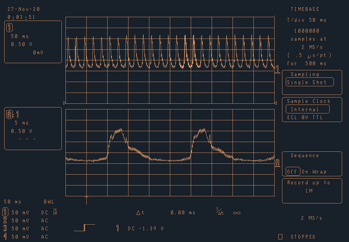
I started by looking at the signal with a white paper covering the ports, as expected, the noise dropped indicating a strong reflection. I proceeded to test it with all ports covered with black tape, and the noise was there, however, due to leakage of light from the LEDs, there was a visible drop i the signal. My next step was to dark-cover a single port on the shroud, I covred the 3rd port that was to be lit up in the sequence with black tape and the rest with white paper, for the first 500ms, the signal was grounded indicating a strong reflection, but then, for 250ms I got a spike in the noise, before returning to be grounded for and extra 250ms. This test was a good indication that I could detect the reflection individually from each port in the shroud. After I was confident the setup worked properly, I put the real test trips onto the shroud and, I tested negative, nope! I’m not pregnant. The only spike indicating a dark band on the test strip was for the second LED pulsed, which was the control line indicating the strip was OK.